Commissioning Tool Procedure:
• In the <Commissioning> section, perform a DL Input Test, UL Input Test, and Isolation Check.
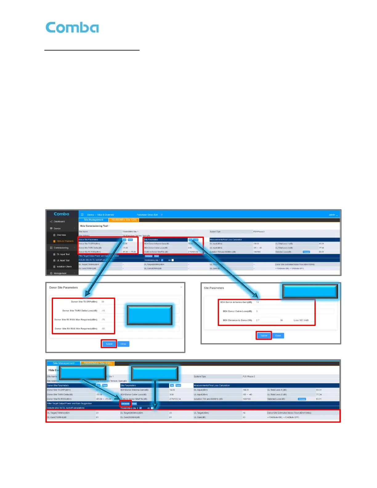
• Navigate to <Sites & Channels> page.
• Click on <Set> in the <Donor Site Parameters> section of the commissioning tool to enter the Donor
Site TX ERP (dBm), Donor Site TX/RX Delta (dB), and the Donor Site RX RSSI (dBm).
• Click on <Set> in the <Site Parameters> section of the commissioning tool to enter the BDA Donor
Antenna Gain (dBd), BDA Donor Cable Loss (dB), and the D. (Mi) to Donor Site/FSL.
• Review the Measurements/Final Loss Calculation section of the GUI and ensure that the DL Input
(dBm), UL Input (dBm), and Isolation 700 and 800MHz (dB) cells have populated with the values
previously obtained by the three commissioning tests. Choose which UL Total Loss to be used. See
the following section Commissioning Tools Calculations Explained for more details.
• In the <Filter Target Output Power and Gain Suggestion> section, click <Generate>.
• The results will be displayed in the lower section of the table.
Note: See Section 3.2 for an explanation of the required RF Inputs required for commissioning. It is
the RF technician’s responsibility to decide if the suggested gain and power values should be used.
If the technician feels confident all the details that have been obtained and entered are correct, and
the suggested values that were generated by the BDA are accurate, they can move forward with
programming these gain and power levels into the GUI. See section 3.29 and 3.30 for setting gain
and power levels.
Figure 130: Using the Commissioning Tool
 Loading...