©2024 Comba Telecom. All Rights Reserved.
568 Gibraltar Drive, Milpitas, CA 95035 | +1 408 526 0180
Commissioning Tool Calculations Explained:
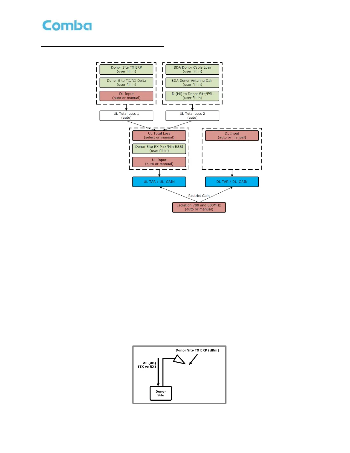
Figure 131 below shows the relationship between all the parameters that are used in the gain and power
calculations.
Figure 131: Commissioning Tool Parameter Calculations Diagram
The RF technician can choose between UL Total Loss 1 or UL Total Loss 2 when generating results in the
commissioning tool. It is recommended to use UL Total Loss 1 as it is based off an actual measurement (DL
Input Test). The UL Total Loss 2 is based on Free Space Loss and does not include any potential clutter
loss. See the following sections for an explanation of UL Total Loss 1 and UL Total Loss 2.
UL Total Loss 1
The 3 parameters below are used to calculate UL Total Loss 1.
UL Total Loss 1 = Donor Site TX ERP + Donor Site TX/RX Delta – DL Input
• Donor Site TX ERP (user fill in): Donor per Channel Output ERP; acquired from licensee or
FCC/ISED web site.
• Donor Site TX/RX Delta (user fill in): BTS RX line loss acquired from licensee. A negative value
would represent an effective Gain on the BTS RX line (e.g. Tower Top Amplifier).
• DL Input (auto or manual): DL Input Power received at the BDA Donor Port. Perform test or
manually write a number in the <Commissioning – DL Input Test> section.
Figure 132: Commissioning Tool – UL Total Loss 1 Parameter Explanation
 Loading...