CRITICALPOINT 700/800MHZ BDA/DAS/BBU V3 USER MANUAL
©2024 Comba Telecom. All Rights Reserved.
568 Gibraltar Drive, Milpitas, CA 95035 | +1 408 526 0180
Rev. 1-0-2 Rev. Date: 11-1-2024
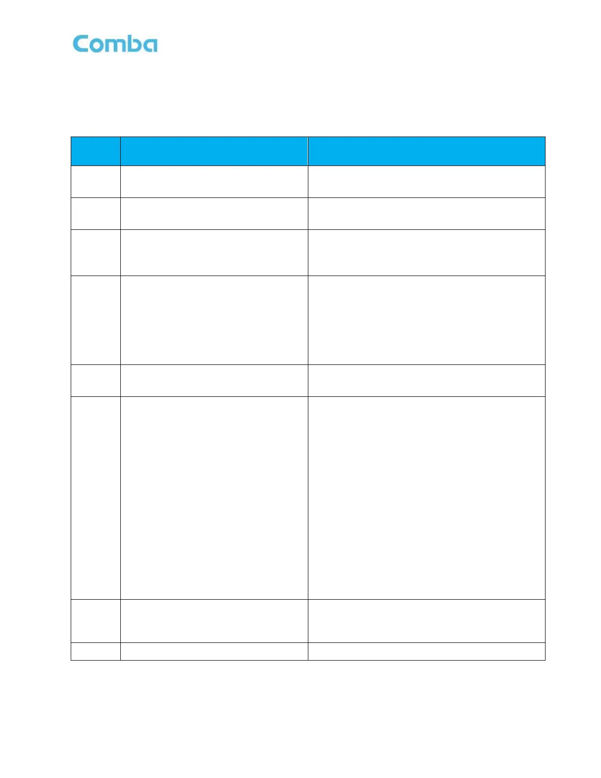
Dry contact alarms 1 through 8 and AP LED’s 1 through 8 are configured according to these standard
presets and the APs will display the alarms accordingly. See Tables 36 through 39 below that describe each
Dry Contact/AP LED preset configuration and the associated internal system alarms that are configured to
trigger them.
Table 36: NFPA 1221 2019 Alarm Preset Dry Contact and LED Operation
Default Alarm Configuration
AC Normal
System Dry ALM 1
AC Lost Alarm
System Dry ALM 2
Charger Fault Alarm
Charger Comm. Fault Alarm
System Dry ALM 3
Battery Low Alarm
Battery Connection Fail Alarm
Battery Over Temperature Alarm
Battery Comm. Fault Alarm
Battery Over Discharge Alarm
System Dry ALM 4
DONOR ANTENNA MALFUNCTION
DT ANT Disconnection Alarm
System Dry ALM 5
ACTIVE RF-EMITTING DEVICE
MALFUNCTION
PA Alarm 700/800 DL/UL
DL P_in Over Alarm 700/800 DL
DL P_out Over Alarm 700/800 DL
LNA Alarm 700/800 DL/UL
Oscillation Shutdown Alarm
Oscillation Gain Reduction Alarm
PLL Alarm
Digital Clock Alarm
VSWR Alarm DL 700/800
Over Temperature Alarm
System OP TX Alarm
System OP RX Alarm
FOU Comm. Fault Alarm (FOU1~4)
System Dry ALM 6
ACTIVE SYSTEM COMPONENT
MALFUNCTION
Same as “ACTIVE RF-EMITTING DEVICE
MALFUNCTION”
System Dry ALM 7
 Loading...