©2024 Comba Telecom. All Rights Reserved.
568 Gibraltar Drive, Milpitas, CA 95035 | +1 408 526 0180
CAUTION. There are two convenient AC Outlets provided next to the AC Input. See
Figure 41. These are to be used for convenience during commissioning for items like
laptops, cell phones chargers, RF Test Equipment, etc. The AC Outlets are in parallel
with the MAIN AC Input and are not backed up by battery power. Do not permanently
connect any components to the outlets for general system use as they will not work
per the code requirements when normal AC power is lost. Furthermore, code
requirements mandate the Signal Booster System Components are fed from a
dedicated circuit. The AC Outlets should be empty during normal operation after
system commissioning.
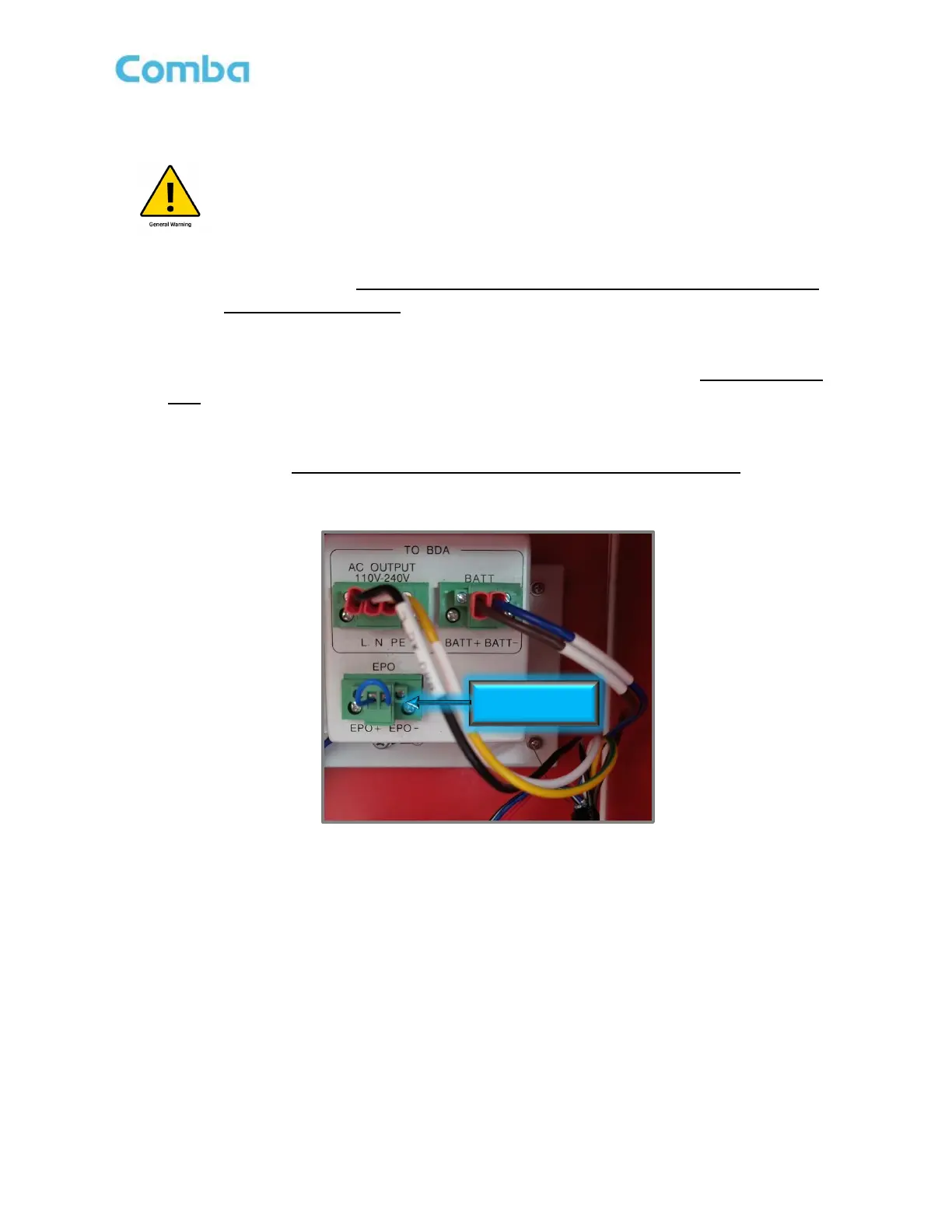
• The EPO connector should be either connected to an external EPO (Require Normally Closed
EPO) or leave it shorted, as shown in Figure 43. If using an EPO switch connect it now. See the
following EPO Wiring Diagram in Figure 44 for more details.
Note: Voltage drop for extension of the EPO should be <20V.
Figure 43: V3 BBU EPO Switch Connection