©2024 Comba Telecom. All Rights Reserved.
568 Gibraltar Drive, Milpitas, CA 95035 | +1 408 526 0180
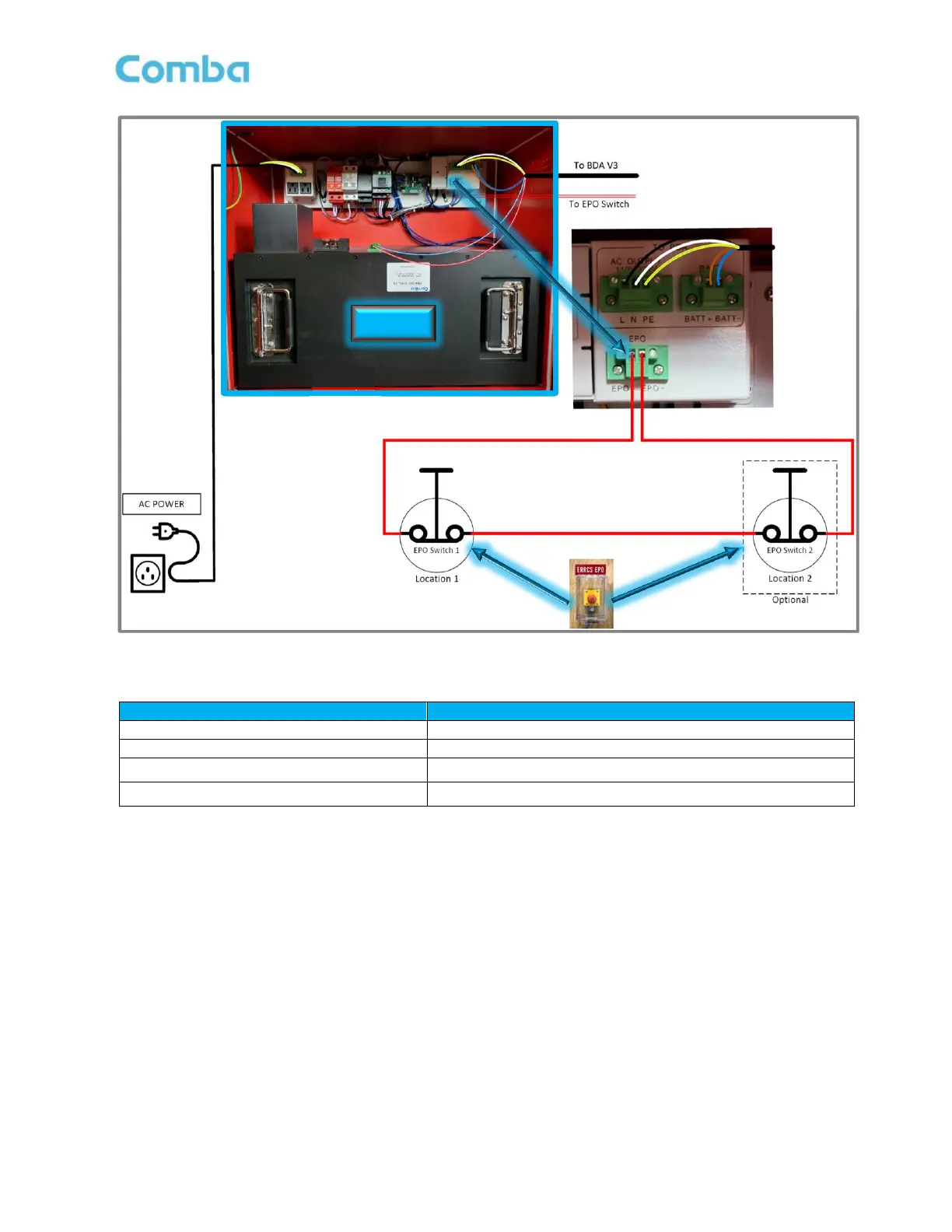
EPO Installation Notes:
1. The EPO connections have a pre-installed wire that shunts the EPO+ and EPO- terminals. Remove
the pre-installed wire and connect the EPO switch; then turn the EPO switch to its “Closed” position
(Normal Status).
2. DO NOT set the EPO switch to “Open” (Cut-off Status).
3. The EPO switch can be installed at a remote location, but the voltage drop should be considered
before installing.
4. The EPO function is triggered from a relay and this relay is energized by the battery or the charger; if
the battery is over-discharged, then the EPO function may not work properly.
5. If you do not wish to use an EPO switch, do NOT remove the pre-installed shorting wire!