©2024 Comba Telecom. All Rights Reserved.
568 Gibraltar Drive, Milpitas, CA 95035 | +1 408 526 0180
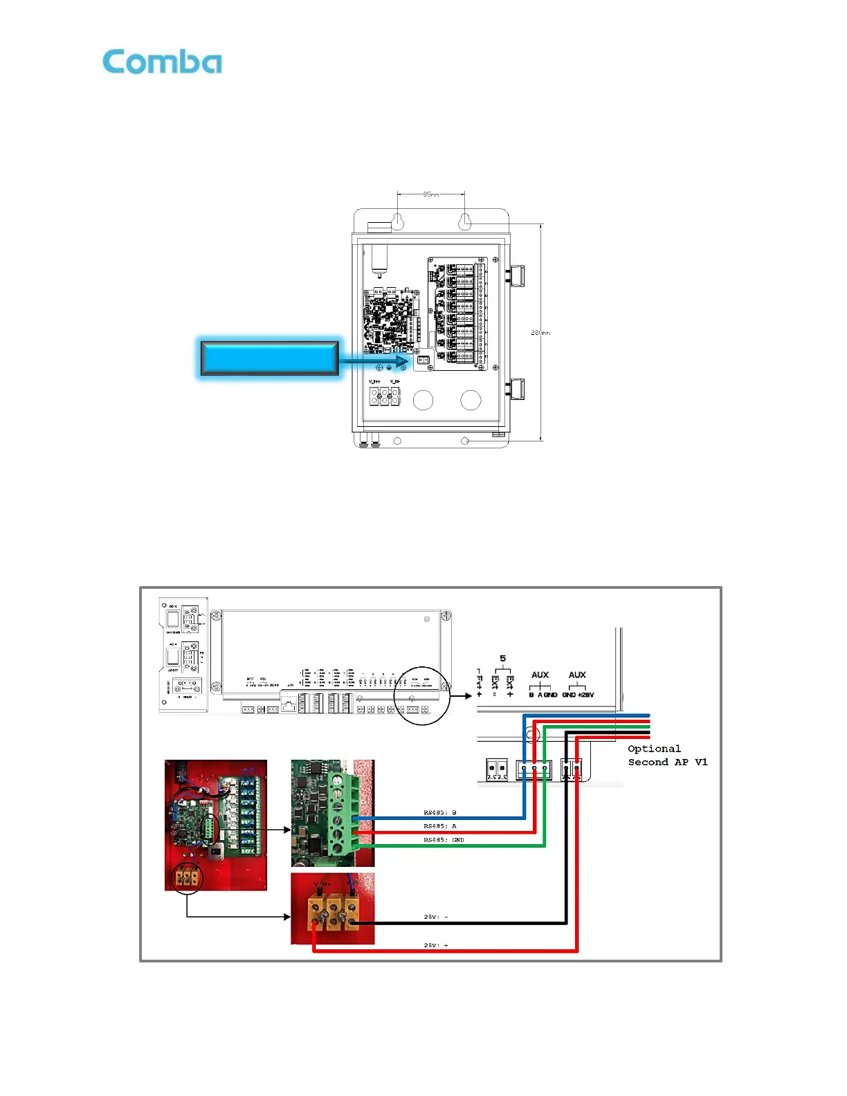
The V1 AP Power and Communications wiring is not provided with the equipment and must be provided by the
installer. Follow the below instructions to connect the V1 AP to the V3 BDA/MU or RU:
• Power down the V3 BDA/MU or RU. Refer to Section 2.13 for the Power Off Switches.
• Ensure the V1 AP Power Switch is in the OFF position. See Figure 58 below.
Figure 58: V1 AP Internal View and Power Switch
• Connect the 3 x RS485 wires between the BDA/MU/RU “AUX” (A, B, and GND) terminals to the V1
AP as shown below in Figure 59.
• Connect the +28VDC and -28VDC Power wires between BDA/MU/RU “AUX” (28VDC and GND)
terminals to the V1 AP as shown below in Figure 59.
Figure 59: V3 BDA/MU and RU – AP V1 Connection