©2024 Comba Telecom. All Rights Reserved.
568 Gibraltar Drive, Milpitas, CA 95035 | +1 408 526 0180
If only using one external V1 AP, the MCU Address Switch can be left in the default position. When using two
V1 APs connected in parallel, you must adjust the Address Switch on the second V1 AP as described below.
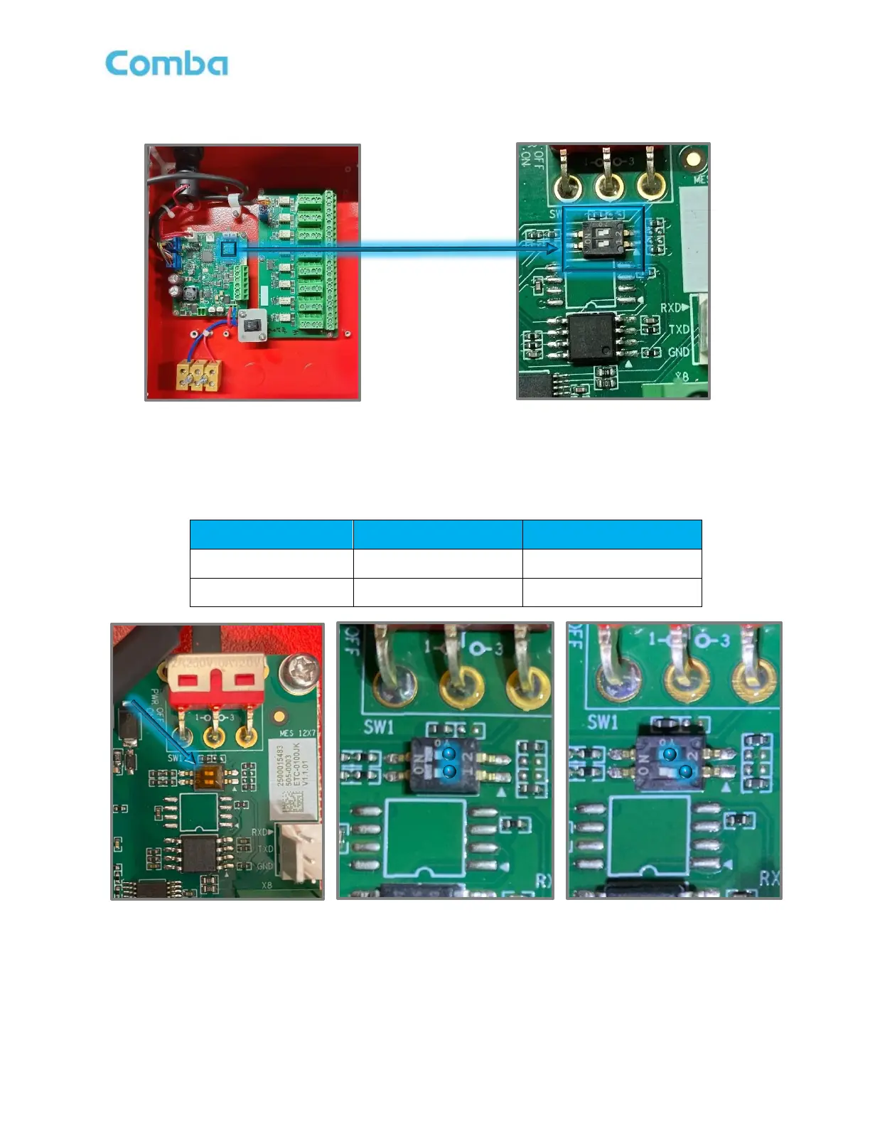
Figure 60: V1 AP MCU Address Setting Switch
When the BDA/MU/RU unit is connected to one external V1 AP, the address of the V1 AP is set to 1. When
BDA/MU/RU unit is connected to two V1 APs, the address is set to 1 and 2, respectively.
Table 8: V1 AP Address Switch Setting
 Loading...