©2024 Comba Telecom. All Rights Reserved.
568 Gibraltar Drive, Milpitas, CA 95035 | +1 408 526 0180
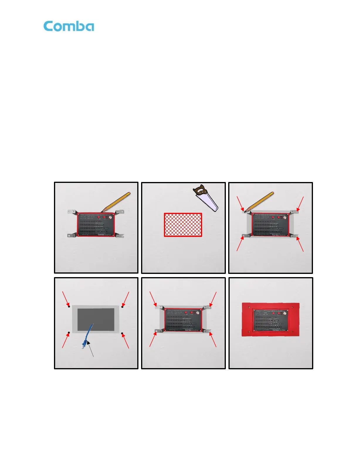
• Using the AP flush mounting bracket as a template, hold the bracket against the wall in the planned
installation location. Using a pencil, trace the sides of the bracket to mark the rectangular location on
the wall that needs to be cut out. Using a saw, cut out the rectangular section of drywall and remove.
• Push the AP mounting bracket into the rectangular area of removed drywall, so it fits flush and tight into
the wall. If the rectangular area is too small to push the bracket into position, you may need to use
sandpaper or another tool to slightly enlarge the rectangular opening.
• Once the AP and Flush Mount Bracket are in position, use a pencil to mark the location of the 4 holes
that will need to be drilled to secure the flush mount bracket to the wall. After hole locations are marked,
remove the AP and flush mount bracket from the wall.
• Drill four holes into the drywall using the previously marked locations. Install wall anchors as necessary.
• Connect the RJ45 ethernet cable to the AP “PREV” port through the flush mount bracket.
• Push AP and flush mount bracket into the wall location.
• Use (4) screws to attach the flush mounting bracket to the wall. Screws and anchors are not provided.
• Install the flush mount front plate using the (4) provided screws.
Figure 75: APV3-BDA - Installing Flush Mount Bracket, APV3-BDA, and Face Plate into a Wall