CP60 and CP60 Plus Service Manual 6-3
General Notes
• After completing replacement procedures, always perform the routine
maintenance procedures in chapter 3 of this manual.
• Verify that the printer functions correctly after replacing parts by performing
and/or observing a limited customer production run.
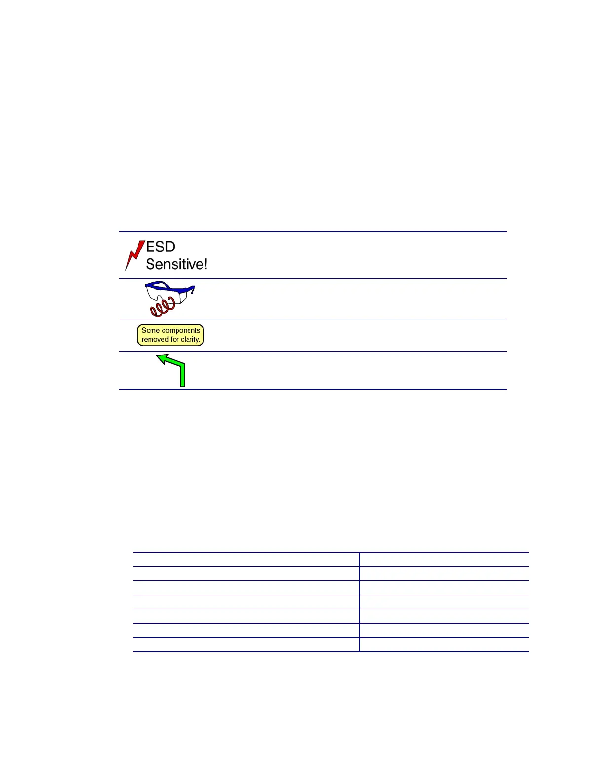
Symbols
Chapter 1 of this manual provides a complete listing of symbol conventions. The
following symbols are used frequently in this chapter, and are repeated here for
convenience.
This symbol is used to designate a procedure that
involves electrostatic discharge sensitive components.
ESD procedures should be used.
This symbol indicates a spring hazard. Safety glasses
should be worn when completing the procedure.
Graphic callouts with a colored background provide
incidental information about the graphic itself.
Graphic leaders with a colored background indicate a
direction of movement or similar information.
Required Tools
• T10 Torx driver
• Slotted screwdriver (standard and small)
• Needle nose pliers
• ESD grounding kit (Part # TUL006-006)
• Protective eye wear
Screw Torque Specifications
Screw Location Torque (in-lbs)
Pick motor 8±0.8
Transport motor 8±0.8
Cam motor 8±0.8
Ribbon take-up motor 8±0.8
680 coupler cable screws 0.9±0.1
Magnetic stripe encoder set screw 1.2±0.1
Magnetic stripe encoder mounting screws 0.9±0.1