6-26 Removal and Replacement
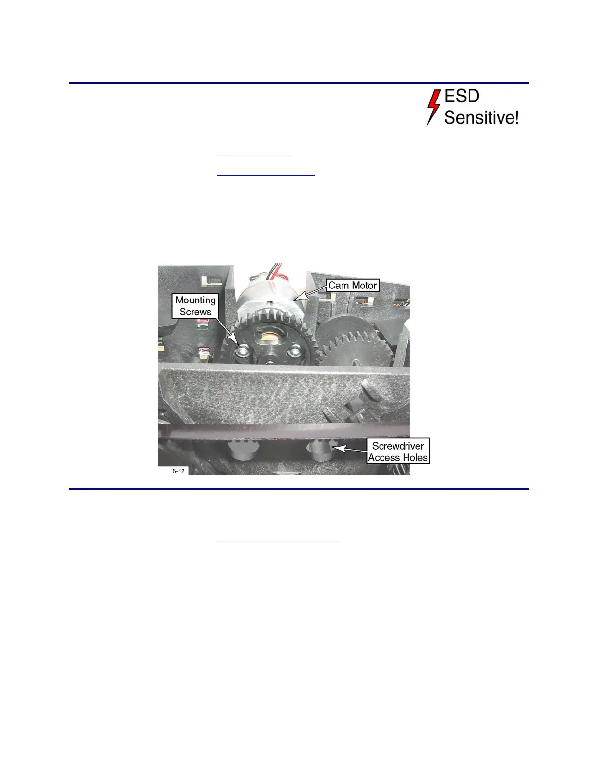
Cam Motor
Removal Procedure
1. Unplug the printer.
2. Remove the ribbon cartridge and cleaning roller.
3. Remove the
Main Enclosure (p. 6-8).
4. Remove the
Transport Assembly from the base (p. 6-29).
5. Rotate the motor gear until the mounting screws are accessible through the
slots.
6. Loosen the two mounting screws, and lift the motor out of the chassis.
(Unless necessary, don’t remove the screws as they can be difficult to
replace.)
Follow-up Procedure
• Tighten the mounting screws to 8 in-lbs.
• Refer to the Functional Block Diagram for replacement details.
• Run the Printhead Cam Test in Diagnostics to verify that the motor is
functional.