Chapter 4 Parameters
4-50
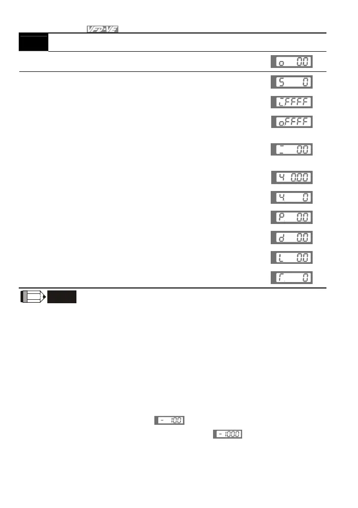
00-04 Content of Multi-Function function Display
17
Display digital output status ON/OFF (Pr.02-15) (o)
(refer to NOTE 4)
U
18 Display multi-step speed (S)
U
19
The corresponding CPU pin status of digital input (i.)
(refer to NOTE 3)
U
20
The corresponding CPU pin status of digital output (o.)
(refer to NOTE 4)
U
21
Number of actual motor revolution (PG1 of PG card).
When the motor direction is changed or drive is stop,
the counter will start from 0 (display will be changed to
0) (Max. 65535) (Z)
U
22 Pulse input frequency (PG2 of PG card) (4)
U
23 Pulse input position (PG2 of PG card) (max. 65535) (4.)
U
F
H
24
Pulse position control for whole operation (MI=37 and
MI=ON) (P.) (refer to NOTE5)
U
25
Display the present reel diameter under the tension
control in mm (d)
U
26
Display the present line speed under the tension control
in m/min (L)
U
27
Display the present tension setting under the tension
control in N (T.)
U
F
H
NOTE
1. When Pr.10-00 is set to 1000 and Pr.10-01 is set to 1/2, the display range for PG feedback will
be from 0 to 4000.
When Pr.10-00 is set to 1000 and Pr.10-01 is set to 3/4/5, the display range for PG feedback
will be from 0 to 1000.
Home position: If it has Z phase, Z phase will be regarded as home position. Otherwise, home
position will be the encoder start up position.
2. It can display negative values when setting analog input bias (Pr.03-03~03-08).
Example 1: assume that AVI input voltage is 0V, Pr.03-03 is 10.0% and Pr.03-06 is 4 (Serve
bias as the center), the display will be
U
.
Example 2: when AUI input voltage is -10V, it will display
U
.
3. Example: If REV, MI1 and MI6 are ON, the following table shows the status of the terminals.
0: OFF, 1: ON