Chapter 4 Parameters
4-177
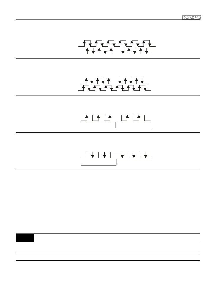
1
Phase A leads in a forward run command and phase B leads in a
reverse run command
A
B
FWD
REV
2
Phase B leads in a forward run command and phase A leads in a
reverse run command
A
B
FWD
REV
3
Phase A is a pulse input and phase B is a direction input. (low
input=reverse direction, high input=forward direction)
A
B
FWD
REV
4
Phase A is a pulse input and phase B is a direction input. (low
input=forward direction, high input=reverse direction)
A
B
FWD
REV
When this setting is different from Pr.10-01 setting and the source of the frequency
command is pulse input (Pr.00-20 is set to 4 or 5), it may have 4 times frequency
problem.
Example: Assume that Pr.10-00=1024, Pr.10-01=1, Pr.10-15=3, Pr.00-20=5, MI=37 and ON,
it needs 4096 pulses to rotate the motor a revolution.
Assume that Pr.10-00=1024, Pr.10-01=1, Pr.10-15=1, Pr.00-20=5, MI=37 and ON, it needs
1024 pulses to rotate the motor a revolution.
10-16 Output Setting for Frequency Division (denominator) Unit: 1
Control
mode
VFPG FOCPG TQCPG
Factory Setting: 1
Settings 1 to 255
This parameter is used to set the denominator for frequency division(for PG card EMV-
PG01L or EMV-PG01O). For example, when it is set to 2 with feedback 1024ppr, PG
output will be 1024/2=512ppr.