Chapter 4 Parameters
4-180
AUI +10V
AUI 0V
AUI -10V
0Hz
ON
frequency
command
output
frequency
resolution
switch
MI=43
forward running
reverse running
Max. frequency for
resolution switch
Pr.10-25
Max. frequency for
resolution switch
Pr.10-25
accel./decel. time
01-12~01-19
Max. output frequency
01-00
Max. output frequency
01-00
waiting time for
switching max.
frequency 10-24
waiting time for
switching max.
frequency 10-24
10-26 Reserved
10-27 Mechanical Gear at Load A1 Unit: 1
10-28 Mechanical Gear at Motor B1 Unit: 1
10-29 Mechanical Gear at Load A2 Unit: 1
10-30 Mechanical Gear at Motor B2 Unit: 1
Control
mode
VFPG FOCPG TQCPG
Factory Setting: 100
Settings 1 to 65535
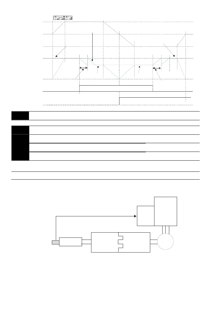
Parameters 10-27 to 10-30 can be used with the multi-function input terminal (set to 48)
to switch to Pr.10-27~10-28 or Pr.10-29~10-30 as shown as follows.
ON =A2:B2
OFF=A 1:B 1
MI=48
Driver
PG
card
Motor
Gear
B1 or B2
Gear
A1 or A2
gear ratio
load
encoder is used
at load side