Chapter 4 Parameters
4-63
01-08 4th Output Voltage Setting 1 Unit: 0.1
Control
mode
VF VFPG
Settings 230V series 0.1 to 255.0V Factory Setting: 0.0
460V series 0.1 to 510.0V Factory Setting: 0.0
01-41 4th Output Frequency Setting 2 Unit: 0.01
Control
mode
VF VFPG SVC FOCPG TQCPG
Factory Setting: 0.00
Settings 0.00~600.00Hz
01-42 4th Output Voltage Setting 2 Unit: 0.1
Control
mode
VF VFPG
Settings 230V series 0.1 to 255.0V Factory Setting: 0.0
460V series 0.1 to 510.0V Factory Setting: 0.0
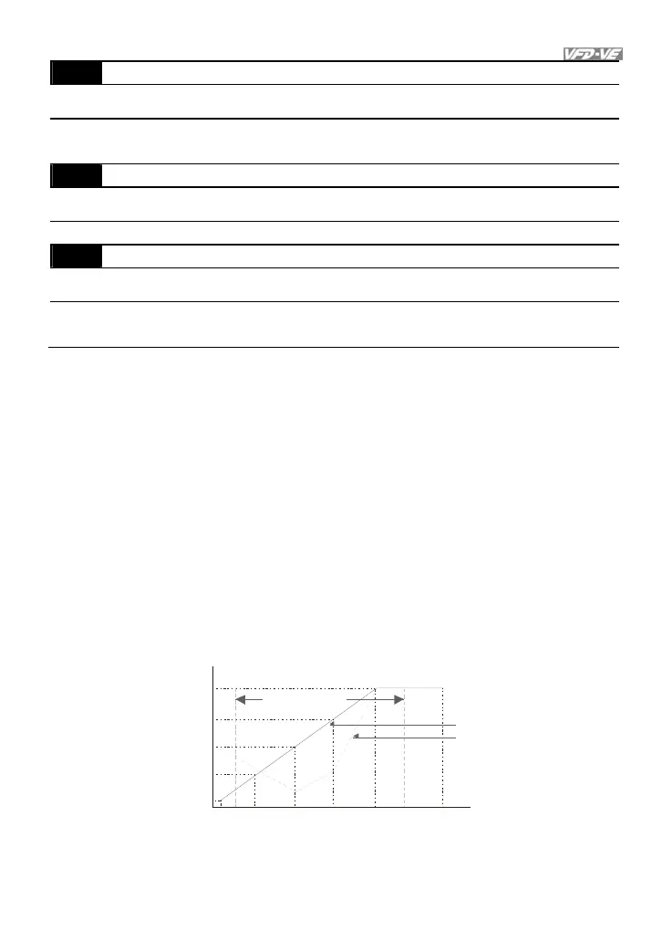
V/f curve setting is usually set by the motor’s allowable loading characteristics. Pay
special attention to the motor’s heat dissipation, dynamic balance, and bearing lubricity,
if the loading characteristics exceed the loading limit of the motor.
For the V/f curve setting, it should be Pr.01-01 Pr.01-03 Pr.01-05 Pr.01-07. There is no
limit for the voltage setting, but a high voltage at the low frequency may cause motor
damage, overheat, stall prevention or over-current protection. Therefore, please use the
low voltage at the low frequency to prevent motor damage.
Pr.01-35 to Pr.01-42 is the V/f curve for the motor 2. When multi-function input terminals
Pr.02-01 to Pr.02-14 is set to 14 and enabled or switch to the -connection, the AC
motor drive will act as the 2nd V/f curve.
The V/f curve for the motor 1 is shown as follows. The V/f curve for the motor 2 can be
deduced from it.
01-05
01-03
01-01
01-06
01-04
01-02
01-0001-07
01-08
01-09
01-11
01-10
1st Ou tput
Voltage Setting
Output Freque ncy
Lower Limit
Frequ ency outpu t
ranges limitat ion
Reg ular V/f Curve
Special V/f Cu rve
Voltage
4th Freq.
Start Freq.
3rd Freq.
2nd Freq.
1st Freq.
Maximum Output
Frequency
V/f Curve
2nd Ou tput
Voltage Setting
3 rd Ou tput
Voltage Setting
4th Ou tput
Voltage Setting
Output Freque ncy
Upp er Limit
Frequ ency