Chapter 4 Parameters
4-49
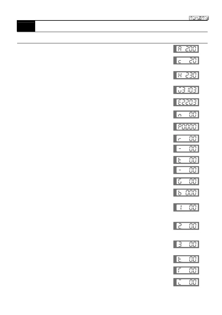
00-04 Content of Multi-Function function Display
Control
mode
VF VFPG SVC FOCPG TQCPG
Factory setting: 0
Settings 0 Display the output current in A supplied to the motor
U
1
Display the counter value which counts the number of
pulses on TRG terminal (c)
U
2
Display actual output frequency (H) with PG feedback/
Display actual electric output frequency without PG
feedback.
U
3
Display the actual DC BUS voltage in VDC of the AC
motor drive (U)
U
4
Display the output voltage in VAC of terminals U, V, W
to the motor (E)
U
5
Display the power factor angle in º of terminals U, V, W
to the motor (n)
U
6
Display the output power in kW of terminals U, V and W
to the motor (P)
U
7
Display the actual motor speed in rpm (enabled when
using with PG card) (r00: positive speed; -00: negative
speed)
U
U
8
Display the estimated value of torque in Nm as it relates
to current (t0.0: positive torque; -0.0: negative torque)
U
U
9 Display PG position (refer to NOTE1)
U
10 Display analog feedback signal value in % (b)
U
11
Display the signal of AVI analog input terminal in %.
Range 0~10V corresponds to 0~100%. (1.) (refer to
NOTE 2)
U
12
Display the signal of ACI analog input terminal in %.
Range 4~20mA/0~10V corresponds to 0~100%. (2.)
(refer to NOTE 2)
U
13
Display the signal of AUI analog input terminal in %.
Range -10V~10V corresponds to -100~100%. (3.) (refer
to NOTE 2)
U
14
Display the temperature of heat sink in °C. (t.)
U
15
Display the temperature of IGBT in °C (T)
U
16
Display digital input status ON/OFF (Pr.02-10) (i) (refer
to NOTE 3)
U