Chapter 2 Installation and Wiring
2-3
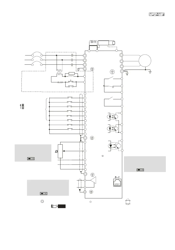
Main circu it ( power) term in als
Con trol c ircui t te rmi nals Shielded l eads & C a ble
Sw1
Si nk
Source
F actor y setting:
SINK Mode
Please r efer t o
Figu re 3 f or w ir in g
of SINK mod e and
SOURCEmode.
R(L1)
S( L2)
T(L3)
Fuse/NFB ( No Fuse Breaker)
SA
OF F O N
MC
MC
RB
RC
Recom men ded Circuit
when p ower supp ly
is t urne d OF F by a
fault output.
R(L1)
S(L2)
T(L3)
E
AVI
ACI
AUI
ACM
+10V
5K
3
2
1
Power supply
+1 0V 2 0m A
M aster F requ ency
0 to 10 V 4 7k
Ana log Si gnal C om mon
E
U(T1)
V(T2)
W(T3)
IM
3~
RA
RB
RC
Mot or
RS-4 85 seri al comm unicati on
1: + EV
2: G ND
3: SG -
4: SG +
5: N C
6: N C
E
DFM
DCM
Di gital F re quency Ou tp ut
Te rminal
fact ory set t ing: 1 :1
D u ty = 5 0% , 1 0 V D C
Digital S igna l Comm on
M ulti-fu ncti on contact o utput 1
(rel ay)
factory setti ng: f aul t i ndi ca tion
MO 1
MO 2
MCM
M ulti-funct i on contact o utput 3
(pho toco upler)
M ulti-fun cti on
Photocoup ler O utp ut
M ulti-funct io n contact o utput 4
(photocou pler)
MRA
MRC
M ulti-fu ncti on contact o utput 2
(rel ay)
48 VDC 5 0mA
factory setting:
i ndica tes that i t i s runn ing
DF M o utput s igna l sel ecti on
MI 1
MI 2
MI 3
MI 4
MI 6
MI 5
DCM
+24V
FW D/S TO P
REV/ST OP
Multi-st ep 1
M ult i- s tep 2
M ulti-step 3
Multi-st ep 4
No functio n
Digita l Sig nal Co mmon
Fact ory
setting
* D on't a pp ly the main s vo ltage d irectly
t o a bove term inals.
E
No functio n
REV
FWD
ACI c urrent/vo ltage sel ection
AFM
ACM
Analo g Signal c om mon
E
T he bra ke r esistor i s buil t-i n to m odel V FD110V 43B -2.NOTE
If the fa ult o ccurs, t he
contact w ill be O N to turn
off the p ower a nd protect t he pow er syst em .
OC TP
DFM Switch
Make sure tha t p ower is OFF
be fore c hangi ng the swi tch
setting.
4~ 20mA/0~1 0V
-10 ~+10 V
0 -20mA 0-10V
ACI S witch
Make sure tha t p ower is OFF
be fore c hangi ng the swi tch
setting .
0~10VDC/2mA
AFM a nal og ou tpu t sel ection
An alog Mul ti-function O utput T ermi nal
0 -10V 0-20m A
AFM S witch
M ake sure that p ow er is O FF
before ch angin g the swit ch
setti ng.
F or com munication,
i t n eeds to use
VFD-USB01/IFD850 0
to conn ect to P C.
i
re 2 f
r
els of
D-
E Series
1
HP
11kW
d ab
e)
VFD150V23A/43A-2, VFD185V23A/43A-2, VFD220V23A/43A-2, VFD300V43A-2, VFD370V43A-2,
VFD450V43A-2, VFD300V23A-2, VFD370V23A-2, VFD550V43C-2, VFD750V43C-2
Jumper
DC choke
(optional)
-(mi nu s si gn )
VFDB
+2
+1
brake un it
(opt ion al)
b rake resist or
(o pti onal )