Chapter 4 Parameters
4-55
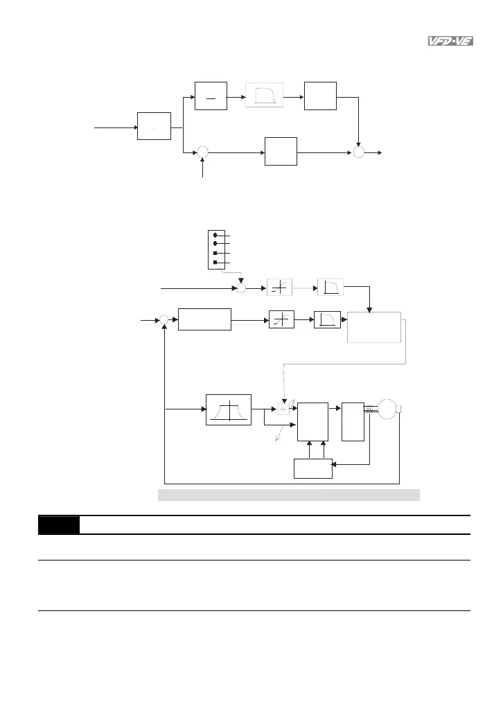
Position control diagram
d
dt
kd
kp
+
-
11-00 bit 0=0
11-18
11-00 bit 0=1
11-11
or
10-2311-17
+
+
A
B
position
command
Electrical gear
10-17
10-18
position
feedback
speed
command
When Pr.00-10 is set to 4, TQCPG control diagram is shown as follows.
10-09
IGBT
&
PWM
M
01-01
01-02
05-01
~05-09
Encoder
10-00
10-01
+
-
+
06-12
07-23
+
no offset
by analog inpu t ( Pr.03-00 )
torque offset setting (Pr. 07-28)
control le d by external ter minal s (Pr.07-2 9 to Pr.07-31)
torque
command
07-21
0 7- 24 or 00 -2 0
spee d l imi t
or command
torque limit
07-32~07-35
actual frequency
Control Diagram for the Torque + Encoder
spee d torq ue
mode switch
Current feedback
Current
control
Current
measure
flux weakeni ng curve
torque command
-
Pr.11-00 Bit 0=0
1 0- 04 ~10 -0 7,
1 0- 21 ~10 -2 2
Pr.11-00 Bit 0=1
11-02~11-04,
11-10~11-11
ASR
lq
command
ld
command
00-11
V/f Curve Selection
Control
mode
VF VFPG
Factory setting: 0
Settings 0 V/f curve determined by group 01
1 1.5 power curve
2 Square curve
When it is set to 0, the V/f curve setting for the motor 1 is according to Pr.01-01~Pr.01-
08 and
Pr. 01-35~01-42 are for the motor 2.