Chapter 4 Parameters
4-26
4.2 Version Differences
4.2.1 Version 2.02
New or update parameter groups are:
Group 2: Digital Input/Output Parameters
Group 3: Analog Input/Output Parameters
Group 6: Protection Parameters
Group 8: High-function PID Parameters
Group 10: Speed Feedback Control Parameters
Version 2.02
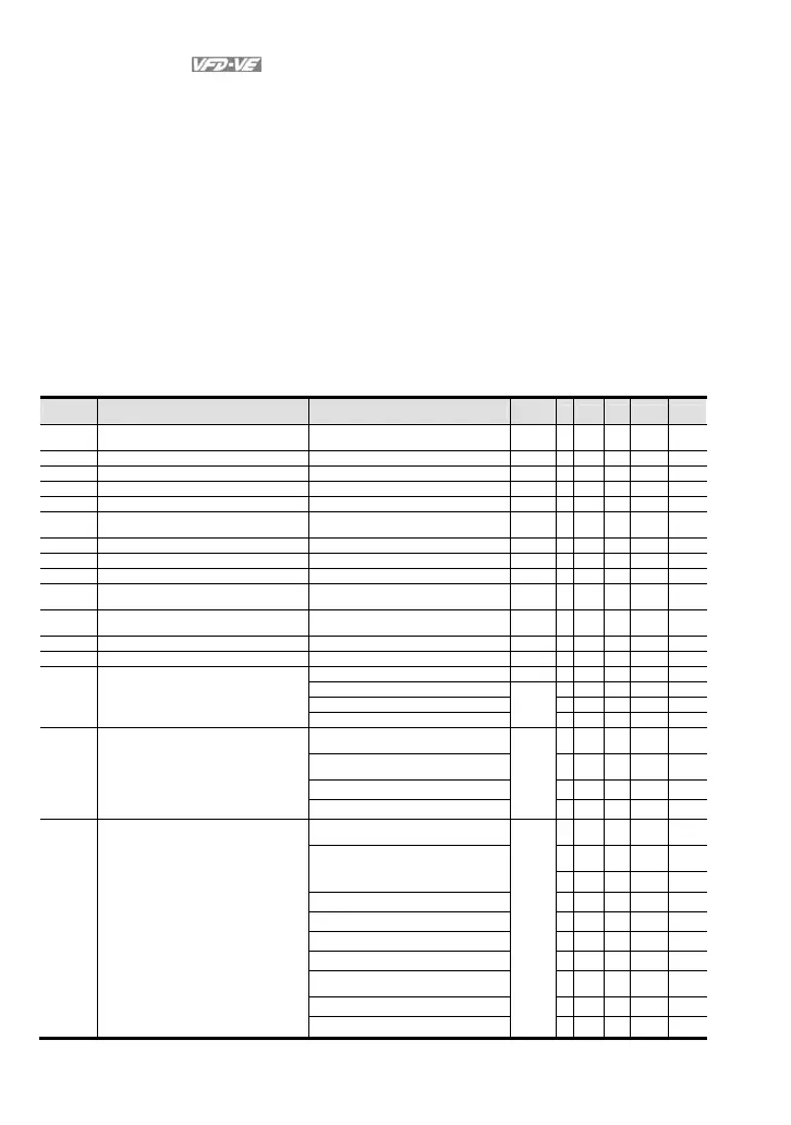
Group 2 Digital Input/Output Parameters
New settings are marked in bold. In version 2.02, the parameters are from Pr.02-00 to Pr.02-34.
Pr. Explanation Settings
Factory
Setting
VF
VFPG
SVC
FOCPG
TQCPG
02-01 Multi-Function Input Command 1 (MI1)
(it is Stop terminal for 3-wire operation)
27: ASR1/ASR2 selection
○
○
02-02
Multi-Function Input Command 2 (MI2) 28: Emergency stop (EF1)
○ ○ ○ ○ ○
02-03
Multi-Function Input Command 3 (MI3) 29: Signal confirmation for Y-connection
○ ○ ○ ○
02-04
Multi-Function Input Command 4 (MI4)
30: Signal confirmation for connection
○ ○ ○ ○
02-05
Multi-Function Input Command 5 (MI5) 31: High torque bias (by Pr.07-29)
○ ○ ○ ○ ○
02-06 Multi-Function Input Command 6 (MI6)
(specific terminal for TRG)
32: Middle torque bias (by Pr.07-30)
○ ○ ○ ○ ○
02-23
Multi-Function Input Command 7 33: Low torque bias (by Pr.07-31)
○ ○ ○ ○ ○
02-24
Multi-Function Input Command 8
34: Enable multi-step position control
○
○
02-25 Multi-Function Input Command 9
35: Enable position control
○
○
02-26 Multi-Function Input Command 10 36: Enable position learning function
(valid at stop)
○
○
02-27 Multi-Function Input Command 11 37: Enable pulse position input
command
○
○
02-28 Multi-Function Input Command 12
38: Disable write EEPROM function
○ ○ ○ ○ ○
02-29 Multi-Function Input Command 13
39: Torque command direction
○
02-30 Multi-Function Input Command 14
40: Force stop
○ ○ ○ ○ ○
41: Serial position clock
○
42: Serial position input
○
43: Analog input resolution selection
○
02-11
Multi-function Output 1 RA, RB,
RC(Relay1)
29: Output when frequency >= Pr.02-33
○ ○ ○ ○ ○
02-12
Multi-function Output 2
MRA, MRC (Relay2)
30: Output when frequency < Pr.02-33
○ ○ ○ ○ ○
02-13
Multi-function Output 3 (MO1) 31: Y-connection for the motor coil
○ ○ ○ ○
02-14
Multi-function Output 4 (MO2)
32: connection for the motor coil
○ ○ ○ ○
02-35
Multi-function Output 5 (MO3) 33: Zero speed (actual output
frequency)
○ ○ ○ ○
02-36
Multi-function Output 6 (MO4) 34: Zero speed with Stop (actual output
frequency)
○ ○ ○ ○
02-37
Multi-function Output 7 (MO5) 35: Error output selection 1 (Pr.06-23)
○ ○ ○ ○ ○
02-38
Multi-function Output 8 (MO6) 36: Error output selection 2 (Pr.06-24)
○ ○ ○ ○ ○
02-39
Multi-function Output 9 (MO7) 37: Error output selection 3 (Pr.06-25)
○ ○ ○ ○ ○
02-40
Multi-function Output 10 (MO8) 38: Error output selection 4 (Pr.06-26)
○ ○ ○ ○ ○
02-41
Multi-function Output 11 (MO9) 39: Position attained (Pr.10-19)
○
02-42
Multi-function Output 12 (MOA) 40: Speed attained (including zero
speed)
○ ○ ○ ○
41: Multi-position attained
○
42: Crane function
○ ○ ○ ○