Appendix B Accessories
B-20 Revision Apr. 2016, 07VE, SW V2.05
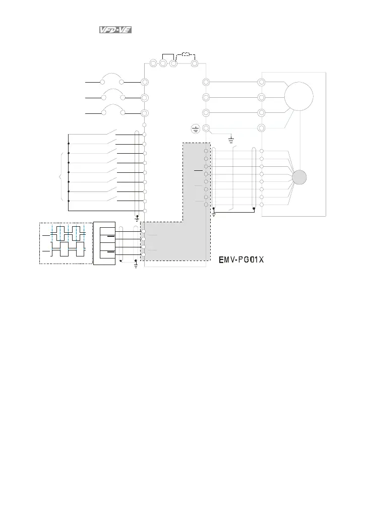
wiring 2
incremental encoder
R/L1
S/L2
T/L3
NFB
R
S
T
+1
+2/B1
B2
U/T1
V/T2
W/T3
-
U
W
V
VP
DCM
A1
A1
B1
B1
Z1
Z1
PG
Line driver
FWD
REV
MI1
MI2
MI3
MI4
MI6
MI5
DC M
24V
M
3~
jumpe
Brake resistor
(optional)
Motor
No-fuse breaker
FWD/STOP
REV/STOP
Multi-step 1
Multi-step 2
Multi-step 3
Multi-step 4
No function
Digital Signal Common
Factory
setting
No function
A2
A2
B2
B2
EH-PLC
Y0
Y0
Y1
Y1
Y0
Y0
Y1
Y1
p h as e d if f er e n c e is 90
o
Example:
It is recommended to set it in TP mode when VFD-VE series inputs the pulse, i.e. inputs pulse from
PLC or host controller into the A2, /A2, B2 and /B2 on the PG card of AC motor drive to prevent the
signal received interference (if using input signal with open collector, please use the external power
(such as PLC power) with a pull-high resistor).