Appendix B Accessories
B-28 Revision Apr. 2016, 07VE, SW V2.05
b. Recommended wire size 0.21 to 0.81mm
2
(AWG24 to AWG18).
3. Wire length: (wire length and signal frequency are in inverse proportion)
Types of Pulse
Generators
Maximum Wire Length Wire Gauge
Output Voltage 50m
1.25mm
2
(AWG16) or above
Open Collector 50m
Line Driver 300m
Complementary 70m
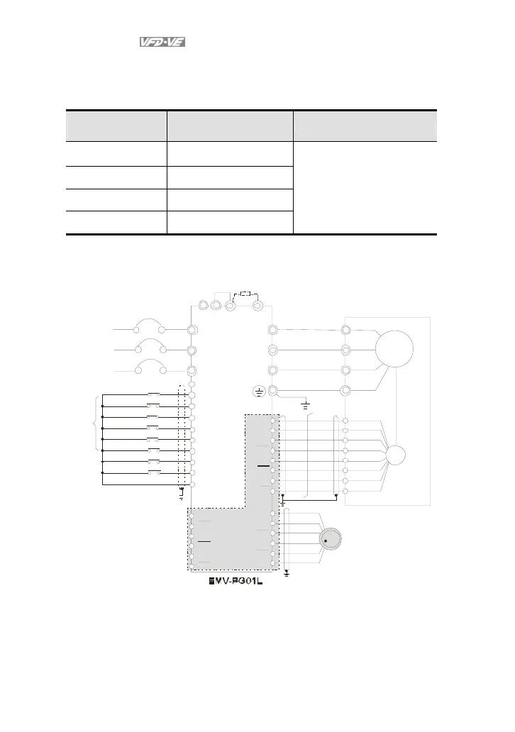
4. Basic Wiring Diagram
wiring 1
R/ L1
S/L2
T/L3
NF B
R
S
T
+1
+2 /B1
B2
U/ T1
V/T2
W/T3
M
3~
-
U
W
V
VP
DC M
A1
A1
B1
B1
Z1
Z1
PG
VP
DCM
A2
A2
B2
B2
10 -1 7
10 -1 8
jumpe
Braking resistor (optional)
Motor
Non -fuse breaker
MI1
MI2
MI3
MI4
MI6
MI5
DCM
+24V
FWD/STOP
REV/STOP
Multi-step 1
Multi-step 2
Multi-step 3
Multi-step 4
No function
Digital Signal Common
Factory
setting
No function
REV
FWD
manua l pulse gener ator
(MPG)
incre mental encoder
Line driverLine driver
Line driver
AO
AO
BO
BO
ZO
ZO