A
B
C
D
E
F
G
H
L
M
N
P
Impianto elettrico
Electric system
sezione / section
P 5
45 SuperSport 800 - M.Y. 2006 - edizione/edition 00
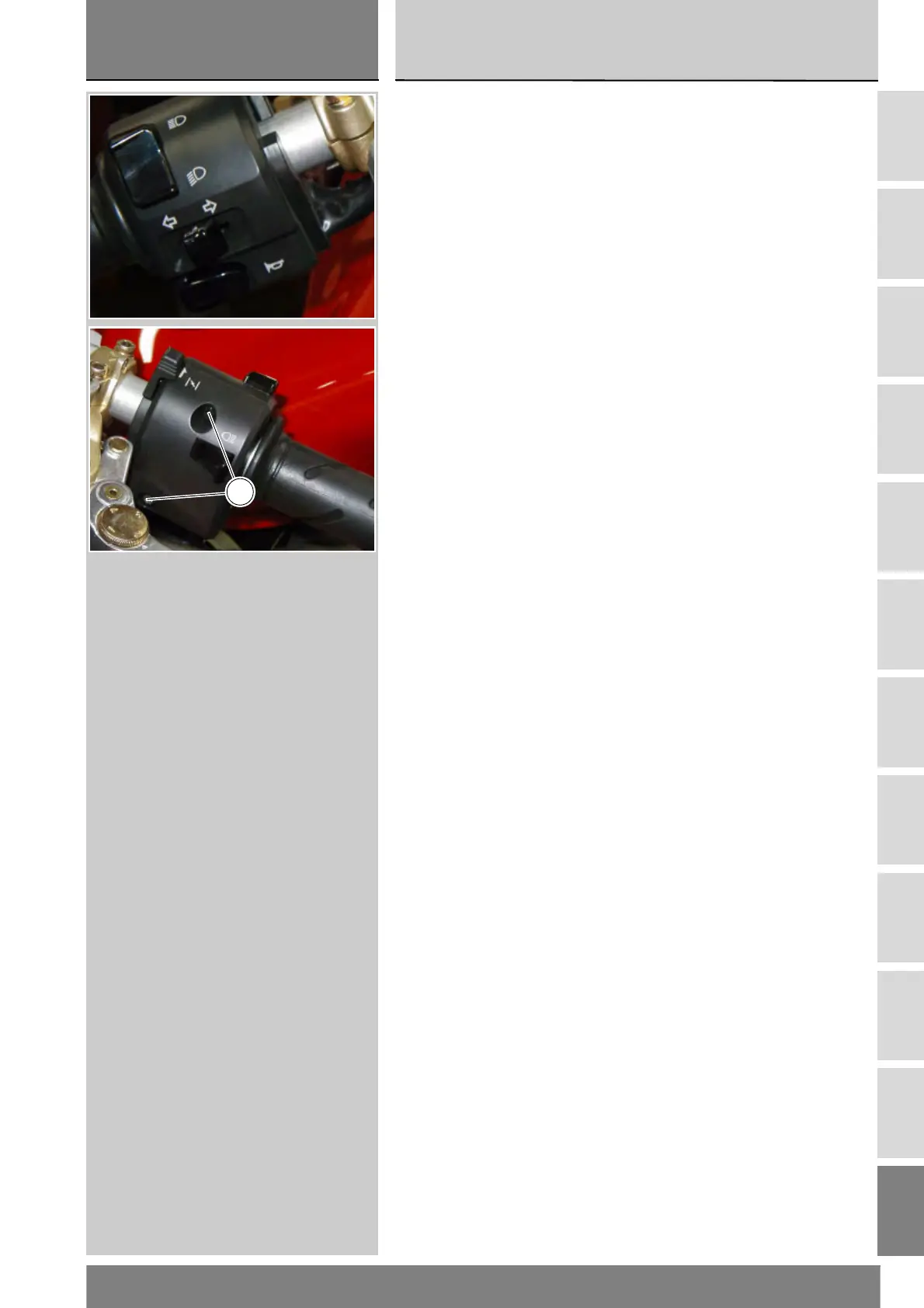
Deviatore indicatori di direzione
(TURN)
Collegare il multimetro sui fili
(Arancio e Grigio) che escono dal
deviatore indicatori di direzione e
verificare che azionando l'indicatore
di direzione destro sia presente
continuità elettrica (Sez. P 9 relativa al
funzionamento del multimetro).
Ripetere lo stesso procedimento per
l'indicatore di direzione sinistro,
collegando il multimetro sui cavi
(Verde e Arancio). I colori citati si
riferiscono ai fili elettrici che escono
dal deviatore e non ai colori dei fili
dell'impianto elettrico principale.
Luci anabbagliante e abbagliante
(DIMMER)
La verifica va fatta con la stessa
procedura, posizionando i tastatori
dello strumento sui cavi:
Luci anabbaglianti (LO)
(Blu/Giallo e Rosso/Giallo)
Luci abbaglianti (HI)
(Rosso/Nero e Blu/Giallo).
Lampeggio (PASSING)
Verificare la continuità tra i cavi
(Rosso/Nero e Grigio).
Rimontare il commutatore sinistro
serrando le viti (1) alla coppia
prescritta (Sez. C 3).
Turn indicator switch (TURN)
Connect the multimeter to Orange
and Grey wires from the turn
indicator switch and check for electric
continuity when operating the right
turn indicator (Sect. P 9 on multimeter
operation).Repeat the above
procedure for the left turn indicator
but connect the multimeter with
Green and Orange cables. Colors
mentioned in the descriptions refer to
the color of wires from the switch and
not to the color of wires of the main
electric system.
Low and high beam (DIMMER)
Test method is the same. Connect
meter as follows:
Low beam (LO)
(Blue/Yellow and Red/Yellow
cables)
High beam (HI)
(Red/Black and Blue/Yellow
cables).
Flasher (PASSING)
Check for continuity across the Red/
Black and Grey cables.
Fit the left switch, tighten the screws
(1) to the specified torque (Sect. C 3).
1
 Loading...