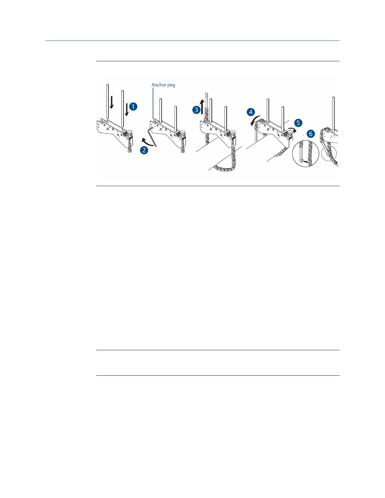
Mount the bracketsFigure 7-8:
Procedure
1.
Insert the support posts into the bracket.
2. Fasten the support posts in place by tightening the hex screws on the sides of the
bracket frame.
3. Place the bracket on the shaft or coupling, wrap the chain around the shaft and feed
it through the other side of the bracket. If the shaft is smaller than the width of the
bracket frame, insert the chain from the inside of the bracket. If the shaft is larger
than the bracket width, insert the chain into the frame from the outside.
4. Catch the chain loosely on the anchor peg.
5. Turn the bracket thumbscrew clockwise to tighten the assembly onto the shaft.
6. Clip the loose end of the chain back onto itself.
The bracket should now be tight upon the shaft. Do not push or pull on the bracket
to check because this could loosen its mounting.
To remove the brackets, turn the thumbscrew counter-clockwise, and then remove
the chain from its anchor peg.
Note
The compact chain-type brackets cover most situations, but in cramped or special cases, other types
of brackets may be required.
7.2.3 Mount the laser and sensor
Horizontal alignment—Mount the laser on the support posts of the bracket fixed on the
shaft of the left machine (usually the reference machine), and the sensor on the support
posts of the bracket fixed on the shaft of the right machine (usually the moveable
machine)—as viewed from a normal working position.
Advanced Laser Alignment
174 MHM-97432 Rev 7
 Loading...


