Vertical alignment—Mount the laser and sensor on either side of the coupling (just like in
horizontal machines), with the laser on the shaft of the machine designated as stationary.
Procedure
1.
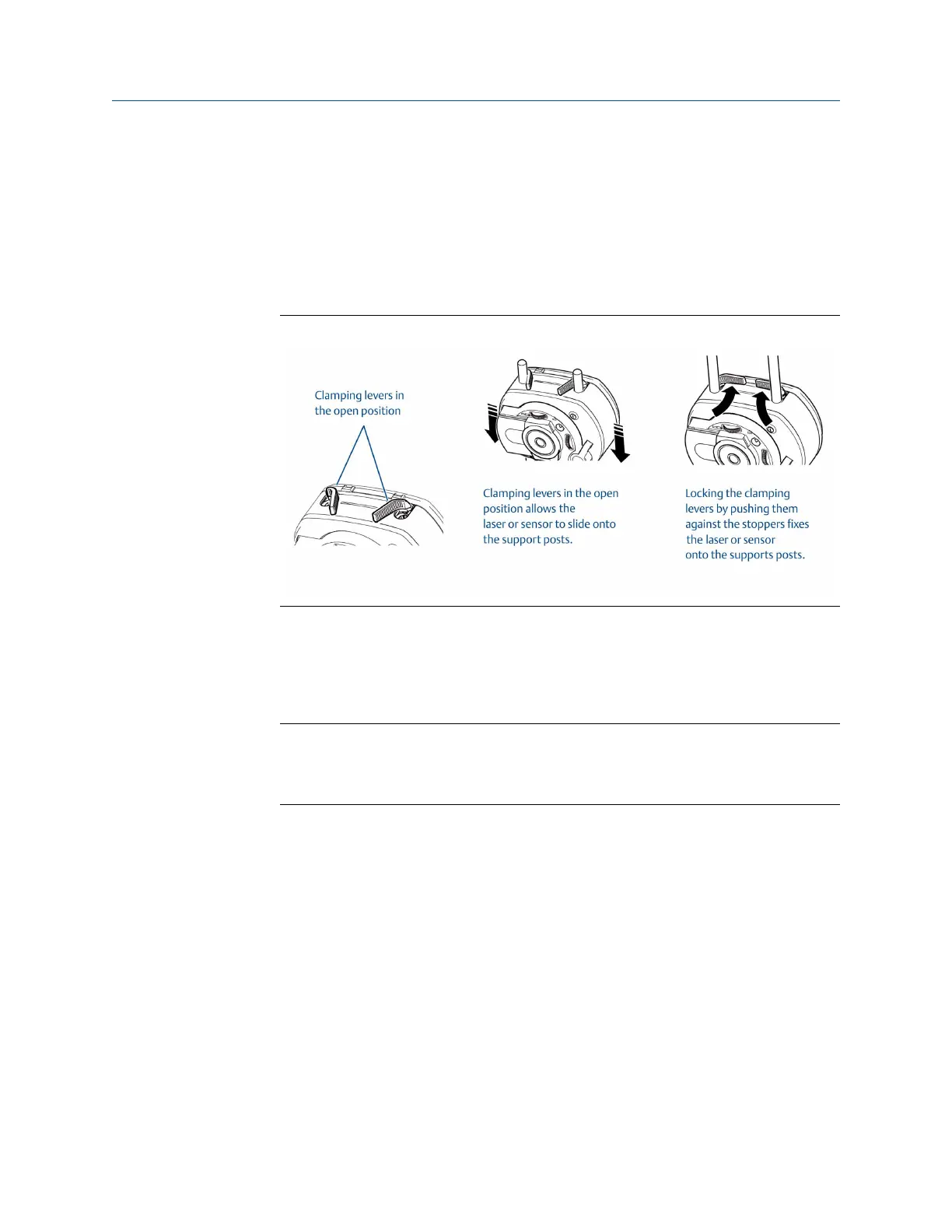
Before mounting the laser and sensor, ensure that the yellow clamping levers are in
the open position by pointing them to the front of the laser and sensor as shown in
Figure 7-9. This enables the laser and sensor to slide onto the support posts.
Clamping leversFigure 7-9:
2. Fix both the laser and sensor onto the respective support posts by locking the yellow
clamping levers. Lock the levers by pushing them backwards until they rest on the
stoppers. Ensure the laser beam can pass over or through the coupling and is not
blocked.
Note
Both the laser and sensor should be at the same height, as low as possible, yet just high
enough for the beam to clear the coupling flange. They should also visually appear to be
rotationally aligned to each other.
Advanced Laser Alignment
MHM-97432 Rev 7 175
 Loading...


