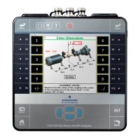
Horizontal live moveFigure 7-36:
Perform the live move with the laser fixtures at any rotational position. Before
proceeding, make sure that the laser fixtures are located at a position where they
can remain stable throughout the alignment process. The average laser and sensor
angle position is displayed in the middle of the screen. The background of the box is
green when the laser fixtures are within 2° of each other, and is white if the laser
fixtures are not within 2° of each other.
For vertical machine moves, if the required movement is positive, the amount of
movement is shown above the machine at the appropriate foot with an up arrow. If
the required movement is negative, the amount of movement is shown below the
machine at the appropriate foot with a down arrow.
For horizontal machine moves, if the required movement is positive, the amount of
movement is shown below the machine at the appropriate foot with a down arrow.
If the required movement is negative, the amount of movement is shown above the
machine at the appropriate foot with an up arrow.
The bottom half of the analyzer screen shows a bull's-eye target and a shaft
centerline plot representing the alignment condition of the machine. The shaft
centerline plot includes a "V" shape indicating the acceptable angular tolerance on
the machine as well as a bracket at the base of the "V" showing the acceptable offset
misalignment at the coupling.
Advanced Laser Alignment
MHM-97432 Rev 7 227

 Loading...


