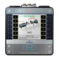
The bottom half of the CSI 2140 screen shows a bull's-eye target and a shaft
centerline plot representing the alignment condition of the machine. The shaft
centerline plot includes a "V" shape indicating the acceptable angular tolerance on
the machine as well as a bracket at the base of the "V" showing the acceptable offset
misalignment at the coupling.
The bull's-eye target compares the total misalignment to the target tolerance. Each
circle in the bull's-eye target has a different meaning: red—more than two times the
tolerance, yellow—between one and two times the tolerance, green—within
acceptable tolerance, green with a star—within excellent tolerance.
a.
Press F2 Repeat Predict Mode to go back to the previous screen.
b. Press F4 Predict Horizontal or F4 Predict Vertical to predict the movement required to
align the machine horizontally or vertically.
c. Press F6 Go to Machine Moves to go back to the Vertical Move, Horizontal Move, or
Dual Move screens from where the predict mode was accessed.
7.5.10 Perform live move - horizontal alignment
The Live Move option lets you observe the machine movement from the analyzer while
you are moving the machine. The option to view live machine moves in the horizontal, or
both the horizontal and vertical directions is dependent upon the setting you chose when
selecting a live move orientation.
Procedure
1. On the Machine Move screen, press F12 Live Move.
Note
This option is present on the Horizontal Move screen by default and is also present depending
on the live move orientation you have previously chosen. See Section 7.4.4.
The screen then displays the movement required to align the machine vertically
and/or horizontally. The bull's-eye target indicates how well the machine is aligned
with respect to tolerances.
Advanced Laser Alignment
226 MHM-97432 Rev 7
 Loading...


