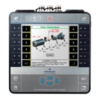
After viewing tolerance plots in QuickSpec mode, press Enter and select from the following:
• Finished—to complete the job.
• Retake Data—to retake data.
• Align Standard Machine—to enter machine dimensions and consider the job as a regular
horizontal alignment job.
• Align C-face Machine—to align a C-face machine. See Section 7.5.12 for more
information on C-face alignment.
7.5.12 C-face alignment
C-face alignment is available only for a QuickSpec job.
Press Enter after viewing the tolerance plots and select Align C-face Machine. See
Section 7.5.11 for more information on a QuickSpec job.
After alignment data is acquired, use the C-face option to display alignment data for
machines with a circular flange and with a basic four-bolt pattern. If the setup for a
rectangular or custom flange pattern is required, change the job to a vertical alignment
job.
Note
You can perform C-face alignment only when the tolerance type is Standard.
1. Set the measurement units for the alignment job. See Section 2.14.8 for more
information.
2.
Enter machine dimensions and press Enter.
Dimension* Measurement description
A Center of the coupling to the flange face
Y Bolt pattern diameter
*Measure to the nearest 1/8 inch (3 mm).
3. View the alignment condition and machine moves for the machine being aligned.
The alignment condition is displayed below the machine graphics.
The bull's-eye target compares the total misalignment to the target tolerance. Each
circle in the bull's-eye target has a different meaning: red—more than two times the
tolerance, yellow—between one and two times the tolerance, green—within
acceptable tolerance, green with a star—within excellent tolerance.
The amount of movement required to align the machine is displayed to the right of
the flange. A graphical representation of the required offset movement
(represented by the dual arrows) is displayed in the center of the flange.
Advanced Laser Alignment
MHM-97432 Rev 7 229

 Loading...


