Show Control 533
Control Change commands were designed to represent specific actions on MIDI devices, like pedals
actuations and effects. For example, the Damper Pedal on a keyboard is often represented by con-
troller number 64 (hex 40). Similar to MIDI Note commands, the MIDI data that is expected to be
received is shown in the CIA and changes as you select event parameters. When finished configuring
the control change event, press {OK} to store the event. Otherwise, press {Cancel} to undo the
changes.
Message Structure
Program change messages have the structure BN XX YYY, where N represents the MIDI channel
number, XX represents the controller number, and YY represents the data byte.
Options
The following options are available:
{Channel}
This should match the MIDI Channel for the note command (1-16, 0-F). If set to Any, the console will
respond when any MIDI channel is sent a note command.
{Controller Number}
The controller number is any value between 0-127 (00-7F). Many devices will display this as 1-128 –
if this is the case for your other device, subtract one from the desired controller number.
{Data}
The data parameter is any value between 0-127 (00-7F). Many devices will display this as 1-128 – if
this is the case for your other device, subtract one from the desired data byte.
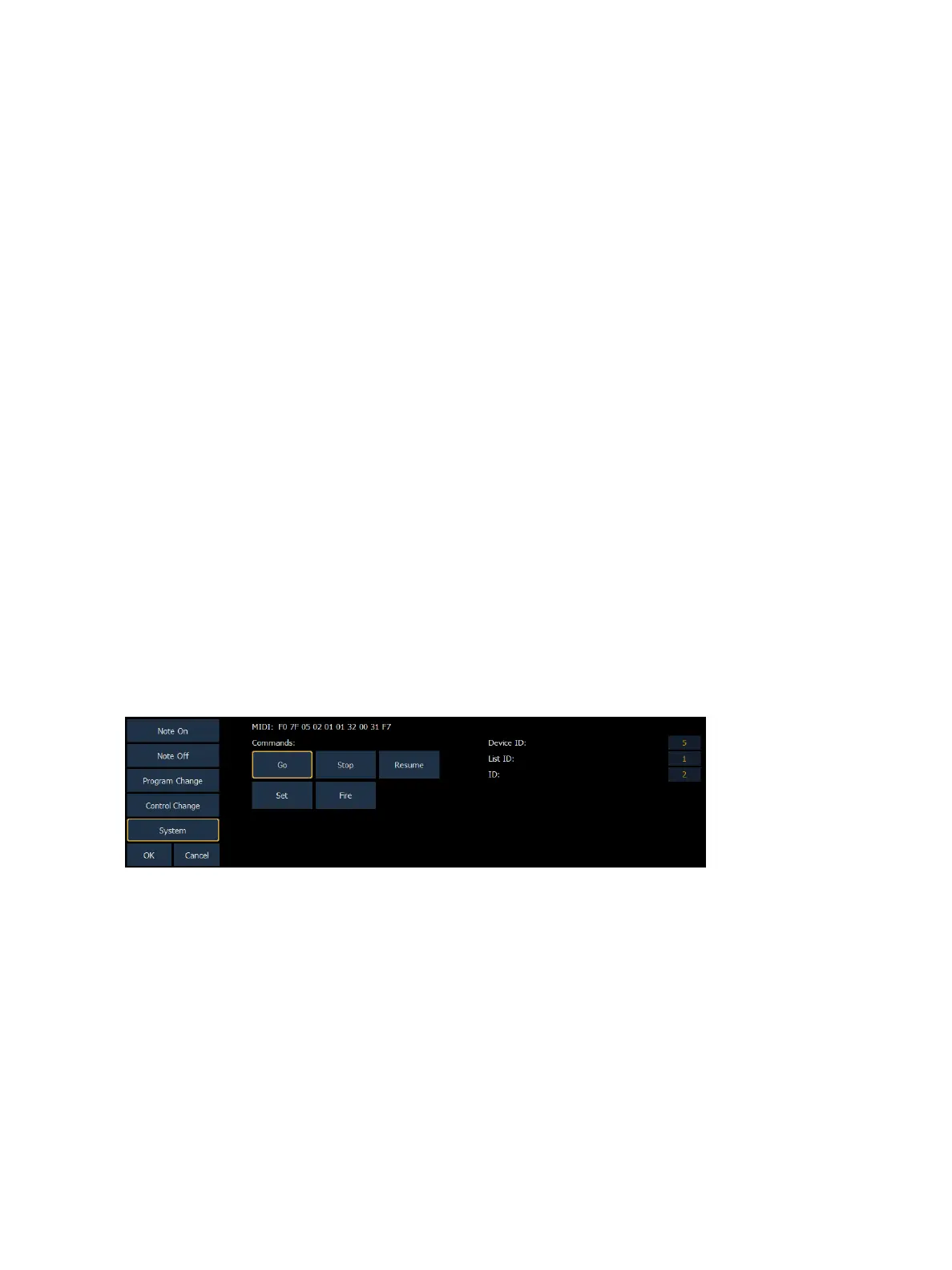
System Events (MIDI Show Control)
System commands allow you to specify specific MIDI Show Control messages that can be received
and interpreted by the console. While any MIDI Show Control command that matches the con-
figured Device ID will be executed normally, this type of event setup allows you to respond to mes-
sages sent to different device IDs, or take additional actions based on a show control command.
The MIDI data that is expected to be received is shown in the CIA and changes as you select event
parameters. When finished configuring the system event, press {OK} to store the event. Otherwise,
press {Cancel} to undo the changes.