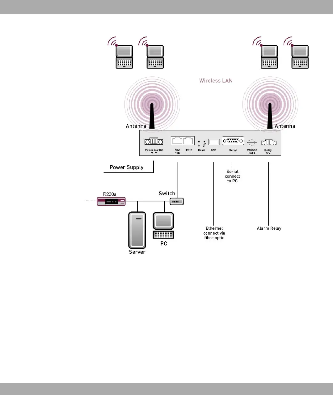
Fig. 3: Connection options bintec WIx040 and bintec WIx060.
When setting up and connecting, carry out the steps in the following sequence (refer to the
connection diagrams for the individual devices in chapter Technical data on page 26):
(1) Antennas
Screw the external standard antennas supplied on to the connections provided for
this purpose.
Put the antennas in the required position before tightening the screw nut. Once the
screw nut has been tightened, it may not be possible to rotate the radiator any more.
If two antennas are connected to the device, these must be installed at least 6 cm
and preferably 12 cm apart so that antenna diversity can be used.
In highly reflective environments, it may make sense to maintain an angle of 90° in
the direction of the antennas. For this, arrange the antennas in a V shape.
(2) Installation
The access points can be fitted to the wall using brackets on the housing or can
3 Installation Funkwerk Enterprise Communications GmbH
8 bintec W1002/W1002n/W2002/WIx040/WIx065