Home
H3C
Server
UniServer R6900 G3
Page 207
H3C UniServer R6900 G3 - Page 207
214 pages
Manual
To Next Page
To Next Page
To Previous Page
To Previous Page
Loading...
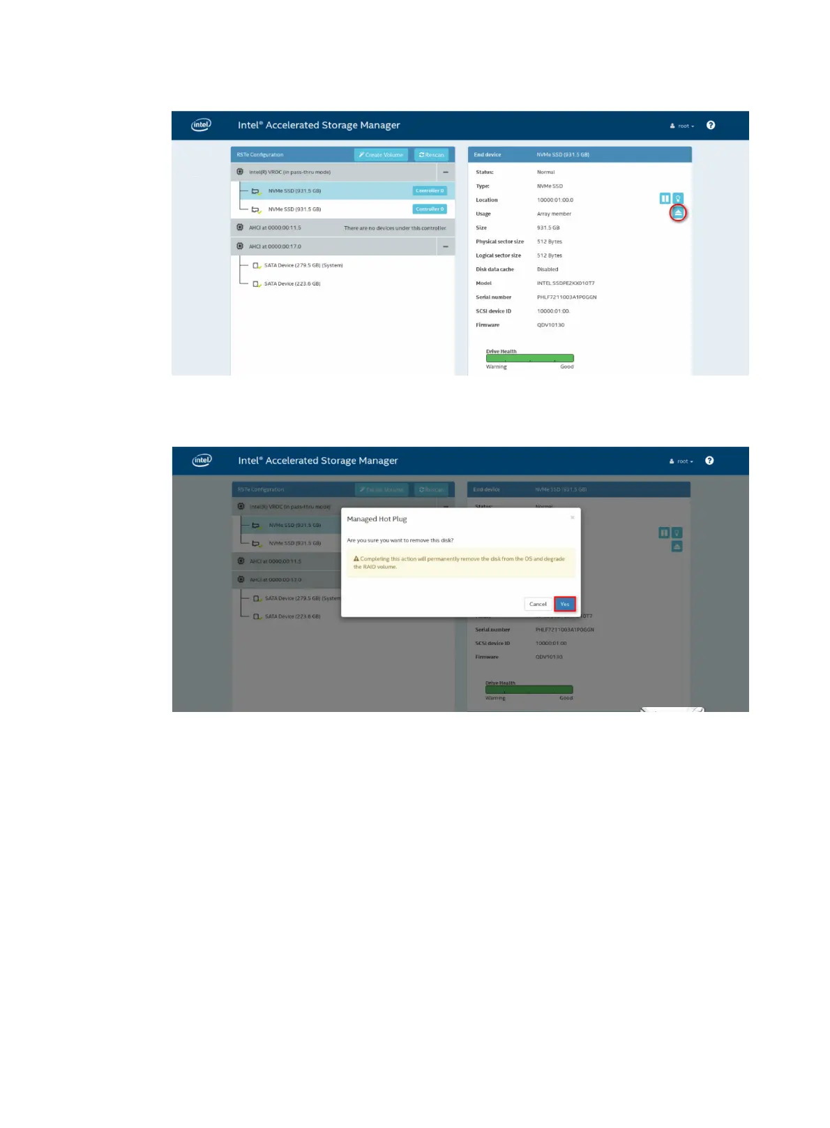
12-5
Figure 12-6 Removing an NVMe drive
8.
In the dialog box that opens, click
Yes
.
Figure 12-7 Confirming the remov
al
9.
Remove the drive from the server. For more
informa
tion about the removal procedure, see
"Replacing an NVMe drive."
206
208
Table of Contents
Main Page
Default Chapter
6
Table of Contents
6
Safety Information
11
Safety Sign Conventions
11
Power Source Recommendations
11
Installation Safety Recommendations
12
General Operating Safety
12
Electrical Safety
12
Rack Mounting Recommendations
12
ESD Prevention
13
Cooling Performance
13
Battery Safety
14
Preparing for Installation
15
Rack Requirements
15
Installation Site Requirements
16
Space and Airflow Requirements
16
Temperature, Humidity, and Altitude Requirements
17
Cleanliness Requirements
17
Grounding Requirements
18
Installation Tools
18
Installing or Removing the Server
20
Installing the Server
20
Installing the Chassis Rails and Slide Rails
20
Rack-Mounting the Server
20
(Optional) Installing the CMA
22
Connecting External Cables
22
Cabling Guidelines
22
Connecting a Mouse, Keyboard, and Monitor
22
Connecting an Ethernet Cable
24
Connecting a USB Device
25
Connecting the Power Cord
26
Securing Cables
28
Removing the Server from a Rack
29
Powering on and Powering off the Server
30
Important Information
30
Powering on the Server
30
Prerequisites
30
Procedure
30
Powering off the Server
31
Guidelines
31
Procedure
31
Configuring the Server
32
Configuration Flowchart
32
Powering on the Server
32
Configuring Basic BIOS Settings
33
Setting the Server Boot Order
33
Setting the BIOS Passwords
33
Configuring RAID
33
Installing the Operating System and Hardware Drivers
33
Installing the Operating System
33
Installing Hardware Drivers
33
Updating Firmware
34
Installing Hardware Options
35
Installing the Security Bezel
35
Installing SAS/SATA Drives
35
Installing Nvme Drives
37
Installing Power Supplies
38
Installing a Compute Module
39
Installing Air Baffles
41
Installing the Low MID Air Baffle or GPU Module Air Baffle to a Compute Module
41
Installing the GPU Module Air Baffle to a Rear Riser Card
43
Installing Riser Cards and Pcie Modules
45
Guidelines
45
Installing a Riser Card and a Pcie Module in a Compute Module
45
Installing Riser Cards and Pcie Modules at the Server Rear
47
Installing Storage Controllers and Power Fail Safeguard Modules
51
Installing GPU Modules
55
Guidelines
55
Installing a GPU Module in a Compute Module
55
Installing a GPU Module to a Rear Riser Card
58
Installing Ethernet Adapters
58
Guidelines
58
Installing an Mlom Ethernet Adapter
58
Installing a Pcie Ethernet Adapter
60
Installing Pcie M.2 Ssds
61
Guidelines
61
Installing a Pcie M.2 SSD in a Compute Module
61
Installing a Pcie M.2 SSD at the Server Rear
63
Installing SD Cards
63
Installing an Nvme SSD Expander Module
65
Installing the Nvme VROC Module
66
Installing a Drive Backplane
66
Installing a Diagnostic Panel
67
Installing Processors
69
Installing Dimms
73
Guidelines
74
Procedure
77
Installing and Setting up a TCM or TPM
79
Installation and Setup Flowchart
79
Installing a TCM or TPM
79
Enabling the TCM or TPM in the BIOS
81
Configuring Encryption in the Operating System
81
Replacing Hardware Options
82
Replacing the Security Bezel
82
Replacing a SAS/SATA Drive
82
Replacing an Nvme Drive
83
Replacing a Compute Module and Its Main Board
84
Removing a Compute Module
84
Removing the Main Board of a Compute Module
85
Installing a Compute Module and Its Main Board
86
Verifying the Replacement
88
Replacing Access Panels
88
Replacing a Compute Module Access Panel
88
Replacing the Chassis Access Panel
89
Replacing a Power Supply
90
Replacing Air Baffles
92
Replacing Air Baffles in a Compute Module
92
Replacing the Power Supply Air Baffle
94
Replacing a Riser Card Air Baffle
95
Replacing a Riser Card and a Pcie Module
97
Replacing the Riser Card and Pcie Module in a Compute Module
97
Replacing a Riser Card and Pcie Module at the Server Rear
98
Replacing a Storage Controller
100
Guidelines
101
Preparing for Replacement
101
Procedure
101
Verifying the Replacement
102
Replacing the Power Fail Safeguard Module for a Storage Controller
102
Replacing a GPU Module
104
Replacing the GPU Module in a Compute Module
104
Replacing a GPU Module at the Server Rear
105
Replacing an Ethernet Adapter
105
Replacing an Mlom Ethernet Adapter
106
Replacing a Pcie Ethernet Adapter
107
Replacing an M.2 Transfer Module and a Pcie M.2 SSD
107
Replacing the M.2 Transfer Module and a Pcie M.2 SSD in a Compute Module
107
Replacing an M.2 Transfer Module and a Pcie M.2 SSD at the Server Rear
109
Replacing an SD Card
109
Replacing the Dual SD Card Extended Module
110
Replacing an Nvme SSD Expander Module
111
Replacing the Nvme VROC Module
112
Replacing a Fan Module
113
Replacing a Processor
115
Guidelines
115
Prerequisites
115
Removing a Processor
115
Installing a Processor
117
Verifying the Replacement
118
Replacing a DIMM
118
Replacing the System Battery
119
Removing the System Battery
120
Installing the System Battery
120
Verifying the Replacement
121
Replacing Drive Backplanes
121
Replacing the Management Module
122
Removing the Management Module
122
Installing the Management Module
123
Replacing the PDB
123
Removing the PDB
124
Installing the PDB
125
Replacing the Midplane
127
Removing the Midplane
127
Installing the Midplane
128
Replacing the Diagnostic Panel
129
Replacing Chassis Ears
129
Replacing the TPM/TCM
131
Connecting Internal Cables
132
Connecting Drive Cables
132
Connecting Drive Cables in Compute Modules
132
Storage Controller Cabling in Riser Cards at the Server Rear
136
Connecting the Flash Card on a Storage Controller
139
Connecting the GPU Power Cord
140
Connecting the NCSI Cable for a Pcie Ethernet Adapter
141
Connecting the Front I/O Component Cable from the Right Chassis Ear
142
Maintenance
143
Guidelines
143
Maintenance Tools
143
Maintenance Tasks
143
Observing LED Status
143
Monitoring the Temperature and Humidity in the Equipment Room
143
Examining Cable Connections
144
Technical Support
144
Appendix A Server Specifications
145
Server Models and Chassis View
145
Technical Specifications
146
Components
147
Front Panel
148
Front Panel View of the Server
148
Front Panel View of a Compute Module
150
Leds and Buttons
151
Ports
152
Rear Panel
153
Rear Panel View
153
Leds
153
Ports
155
Main Board of a Compute Module
155
Main Board Components
155
DIMM Slots
156
Management Module
157
Management Module Components
157
System Maintenance Switches
158
Pdb
159
Appendix B Component Specifications
160
About Component Model Names
160
Software Compatibility
160
Processors
160
Intel Processors
160
Jintide-C Series Processors
162
Dimms
162
DRAM Specifications
162
DCPMM Specifications
163
DRAM DIMM Rank Classification Label
163
Hdds and Ssds
164
Drive Specifications
164
Drive Leds
167
Drive Configurations and Numbering
168
Pcie Modules
173
Storage Controllers
174
Nvme SSD Expander Modules
179
GPU Modules
179
Pcie Ethernet Adapters
181
FC Hbas
182
Mlom Ethernet Adapters
185
Riser Cards
185
Riser Card Guidelines
186
Rs-Fhhl-G3
186
Rs-Gpu-R6900-G3
186
Rs-4*Fhhl-G3
187
Fhhl-G3-1
188
Fhhl-G3-2
189
Fan Modules
191
Air Baffles
192
Compute Module Air Baffles
192
Power Supply Air Baffle
193
Rear Riser Card Air Baffles
193
Power Supplies
194
800 W Power Supply
194
800 W High-Voltage Power Supply
194
1200 W Power Supply
195
850 W High-Efficiency Platinum Power Supply
196
Expander Modules
196
Diagnostic Panels
197
Diagnostic Panel Specifications
197
Diagnostic Panel View
197
Leds
197
Fiber Transceiver Modules
201
Storage Options Other than Hdds and Sdds
201
Nvme VROC Modules
201
TPM/TCM Modules
201
Compute Modules
202
Security Bezels, Slide Rail Kits, and CMA
202
Appendix C Managed Hot Removal of Nvme Drives
203
Performing a Managed Hot Removal in Windows
203
Prerequisites
203
Procedure
203
Performing a Managed Hot Removal in Linux
204
Prerequisites
204
Performing a Managed Hot Removal from the CLI
204
Performing a Managed Hot Removal from the Intel ® ASM Web Interface
205
Appendix D Environment Requirements
208
About Environment Requirements
208
General Environment Requirements
208
Operating Temperature Requirements
208
Appendix E Product Recycling
210
Appendix F Glossary
211
Appendix G Acronyms
213
Other manuals for H3C UniServer R6900 G3
Operating System Installation Guide
105 pages
Installation, Quick Start
15 pages
Related product manuals
H3C UniServer R4900 G3
401 pages
H3C UniServer R4700 G3
401 pages
H3C UniServer R4950 G3
401 pages
H3C UniServer E3200 G3
401 pages
H3C UniServer R4900 G5
401 pages
H3C UniServer R4700 G6
45 pages
H3C UniServer R4950 G5
401 pages
H3C UniServer R4300 G6
542 pages
H3C UniServer R4900 G6 Ultra
74 pages
H3C UIS-Cell 3000 G3
171 pages

 Loading...


