6-36
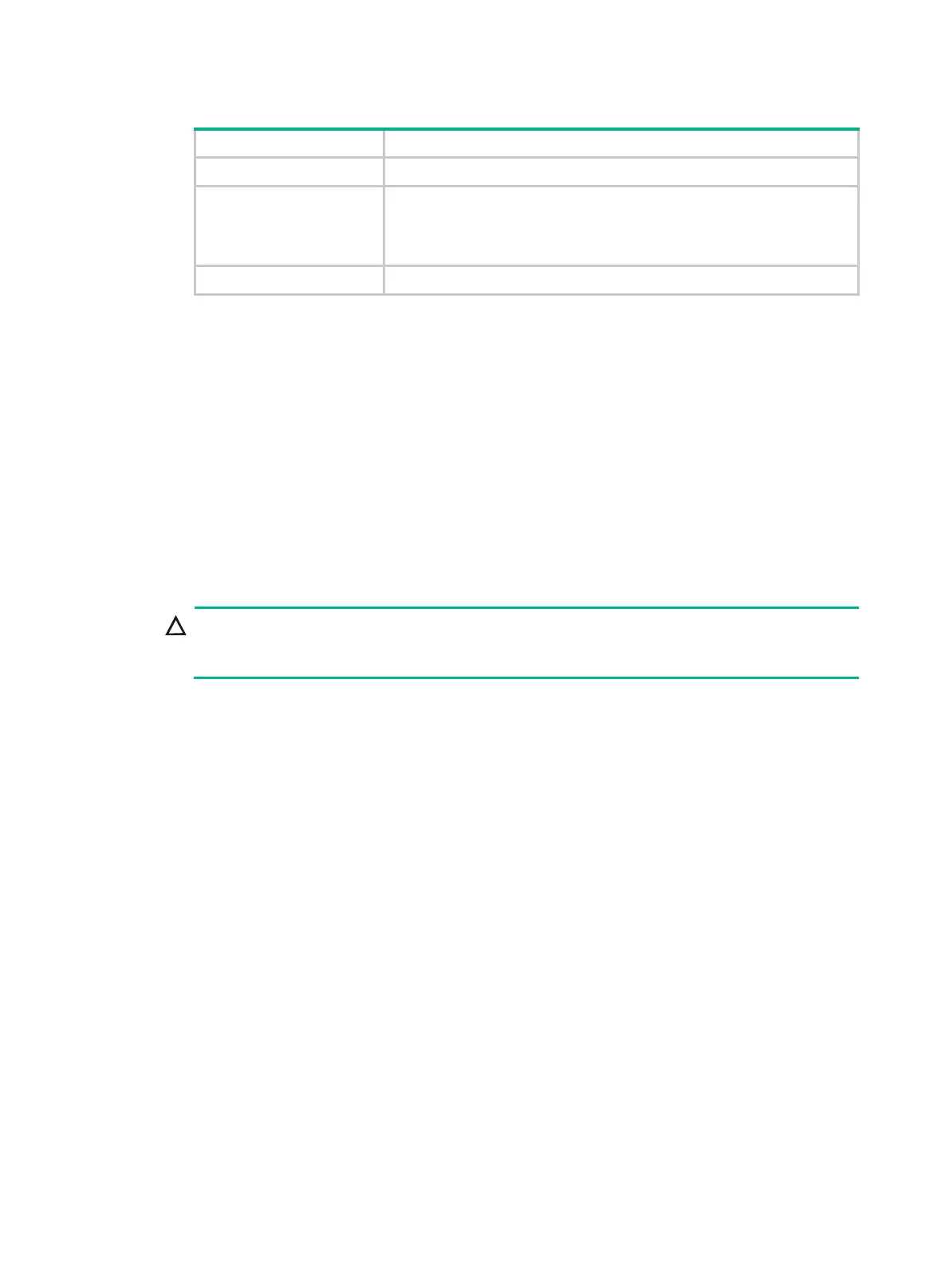
Table 6-2 Process installation locations
Number of processors Installation locations
1 Socket 1 of compute module 1.
2
• For processors of model 5xxx, install a processor in socket 1 of
compute module 1 and the other in socket 1 of compute module 2.
• For processors of model 6xxx or 8xxx, install both processors in
compute module 1.
4 Install the processors in all sockets.
• For the location of compute modules, see "Front panel view of the server." For the location of
processor sockets, see "Main board components."
Procedure
1. Back up all server data.
2. Power off the server. For more information, see "Powering off the server."
3. Remove the
security bezel, if any. For more information, see "Replacing the security bezel."
4. Remove the compute module. For more information, see "Removing a compute module."
5. Remove the compute module access panel. For more information, see "Replacing a compute
module a
ccess panel."
6. Remove the air baffles that might hinder the installation in the compute module. For more
information, see "Replacing air baffles in a compute module."
7. Install a processor onto the retaining bracket, as shown in Figure 6-42:
CAUTION:
To avoid damage to the processor, always hold the processor by its edges. Never touch the
gold contacts on the processor bottom.
a. As shown by callout 1, align the small triangle on the processor with the alignment triangle in
the retaining bracket, and align the guide pin on the bracket with the notch on the triangle
side of the processor.
b. As shown by callout 2, lower the processor gently and make sure the guide pins on the
opposite side of the bracket fit snugly into notches on the processor.

 Loading...


