VALVE
IV
ALVE
GUIDE
Disassemble the cylinder head (page 8-12),
Check that t
he
valve moves smoothly in the guide.
Check each valve for bend, burn, scratch or abnormal
wear.
Measure each valve stem 0 .
0.
and
record
it.
SERVICE LIMIT:
IN
: 4.965 mm (0.1955 In)
EX
: 4.945 mm
(0
.1947
In)
CYLINDER HEADNALVES
Always fOlale/he
reamsr
clockwise,
never
counterclockwise
when
inserting,
removing and
reaming.
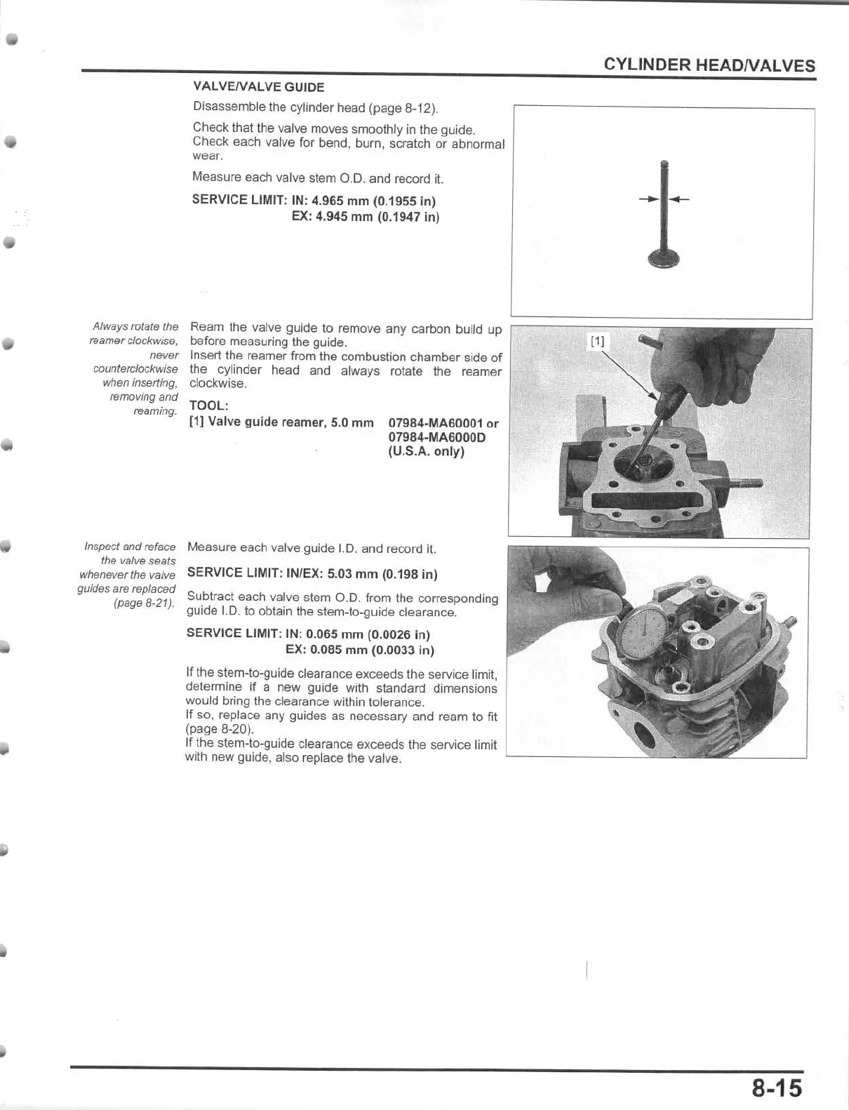
Ream
the
valve guide
to
remove any carbon
bu
ild up
~
======
==::;:
:::;;;;
;;;;;;
;;;::::;:
~
before measuring t
he
guide.
Insert the reamer from the combustion
chamber
side
of
the cylinder head and always rotate the reamer
clockwise.
TOOL:
[1J
Valve
guide
reamer, 5.0
mm
07984·MA60001or
07984-
MA60000
(U
.S.A.
only)
Inspect and reface Measure each valve guide 1.0. and record
it.
the valve
seals
whenever the valve
guides
are replaced
(page
8-21).
SERVICE LIMIT: IN/
EX
: 5.03
mm
(0.
198
in
)
Subtract each valve stem O.D. from the corresponding
guide I.D. to obtain the stem-to.guide
dearance
.
SERVICE LIMIT: IN: 0.065
mm
(0.0026
in)
EX: 0.085
mm
(0.0033 In)
If the stem-to-guide clearance exceeds t
he
service limit,
determine if a new guide with standard dimensions
would bring the clearance within tolerance.
If so. replace any guides as necessary and ream to fit
(page 8-20).
If
the stem-to.guide clearance exceeds the service limit
with new guide, also replace the valve.
8-15