VALVE CLEARANCE
INSPECTION
Inspect
and
adjust Remove
the
cyli
nder h
ead
cover (page 8-6).
the valve clearance
while the engine is
cold (be/ow
35
'
C/
9S
'
F)
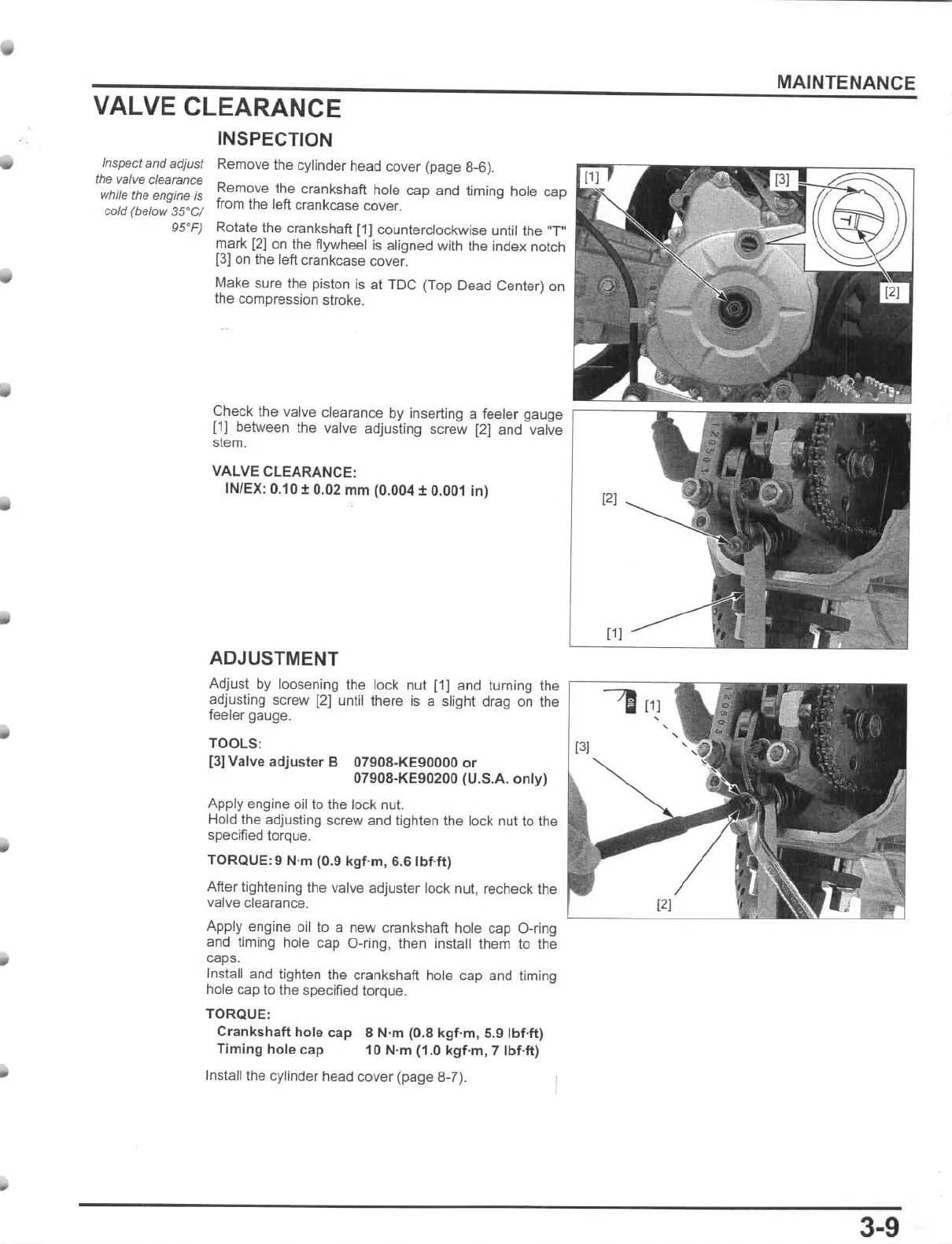
Remove the crankshaft hole cap and liming hole cap
from the left crankcase cover.
Rotate the crankshaft
[1J
counterclockwise unl
illhe
"r
mark
[2]
on the flywheel is aligned with the index notch
13J
on the left crankcase cover.
Make sura the piston is at TDC (Top Dead Center) on
the
compression stroke.
Check the valve clearance by inserting a feeler gauge
,---
-,
r-
- --,
[1)
between the valve adjusting screw
121
and valve
st
em.
VALVE CLEARANCE:
IN
/
EX
: 0.
10
t 0.02
mm
(0
.004 ± 0.001 in)
ADJUSTMENT
Adjust by loosening the lock nut
111
and turning the
,----::
::--
-
adjusting screw
(2
) until there is a slight drag
on
the
~
feeler gauge.
TOOLS:
[3J
[3) Valve
adju
ster B 07908·KE90000
or
07908-KE90200
(U
.S.A.
only)
Apply engine oil to the lock nul.
Hold the adjusting
sc
rew and tighten the lock nut to
the
specified torque.
TORQUE:9 N·m (0.9
kgf
·m, 6.
6Ibf
·ft)
After tightening the valve adjuster lock nut, recheck t
he
valve dearance.
Apply engine oil to a new crankshaft. hole cap a-ring
an
d timing hole cap D-ring, then install them
to
the
caps.
Install and tighten the crankshaft hole cap and timing
hole cap to the specified torque.
TORQUE:
Crankshaft
hole cap 8 N·m (0.8
kgf
·
m,
5.9 Ibf-ft)
Timln9
hole
cap 10 N·m
(1
.0
kgf·m
,
7Ibf-ft)
Install
the
cylinder head cover (page 8·7).
MAINTENANCE
3-9