IGNITION SYSTEM
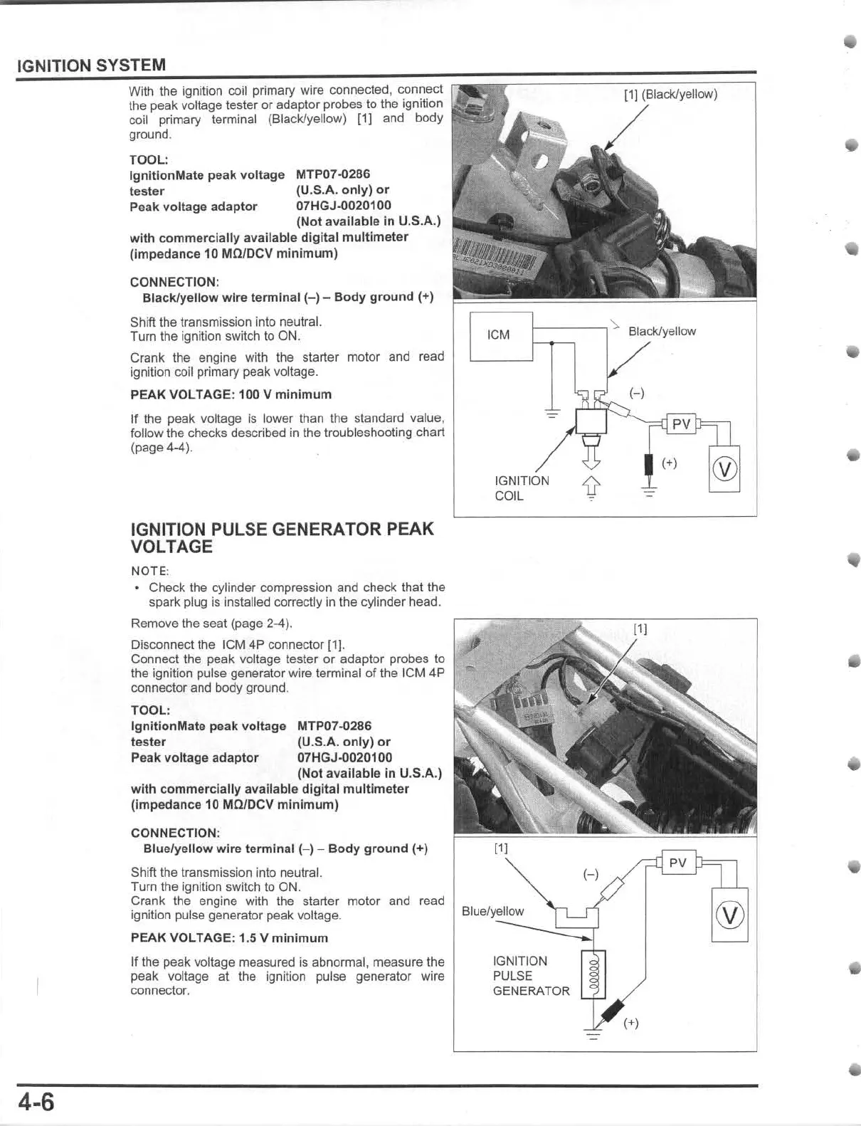
With the ignition coil primary wire connected, connect
the peak voltage tester or adaptor probes to the ignition
coil primary terminal (Blacl<Jyellow) [1] and body
ground.
TOOL
:
Ignition
Mate
peak
voltage
tester
P
eak
vo
ltage
adaptor
MTP07-0286
(U
.S.A.
only)
or
07HGJ-0020100
(N
ot
available
in
U.S.A.)
with
commercially
available
digital
multimeter
(Impedance
10 MO/DCV
minimum)
CONNECTION:
Bl
ack/ye
llow
wire
te
rmin
al (
-)
-
Body
ground
(+)
Shlft the transmission into neutral.
Tum
the ignilion switch to ON.
Crank the engine with the starter motor and read
ignition coil primary peak voltage.
[1J
(Black/yellow)
1
~'
~C~
M
~1---~
:..
Black/yellow
PEAK
VOLTAGE
: 100 V
minimum
(
-)
4-6
If the peak vo!\age is lower than the standard value,
follow the checks described
in
the troubleshooting chart
(page 4-4).
IGNITION PULSE GENERATOR
PEAK
VOLTAGE
NOTE
:
• Check the cylinder compression and check
Ihallhe
spark plug is installed correctly
in
the cylinder head.
Remove the seat (page 2-4),
Disconnect the
leM
4P connector (1].
Connect Ihe peak voltage laster
or
adaptor probes to
the ignition pulse generator wire terminal
of
the leM 4P
connector
and
body
ground
.
TOOL
:
IgniiionMate
peak
voltage MTP07-0286
tes
ter
(U
.S.A.
on
ly)
or
Peak voltage
adaptor
07HGJ-0020100
(Not
available
in
U.S.A.)
wit
h commercially available
digital
multlmet
er
(impedance
10 MQ/DCV
minimum)
CONNECTION:
Blue
/ye
llow
wire
terminal
(-)
-
Body
ground
(+)
Sh
i
ft
the transmission into neutral.
Turn the ignition switch to ON.
Crank the engine with the starter motor
and
read
ignition pulse generator peak voltage.
PEAK
VOLTAGE: 1.5 V
minimum
If the peak voltage measured is abnormal, measure the
peak voltage at the ignition pulse generator wire
connector.
(+)
®
IGNITION
'if
COIL
-
(-
)
Blue/yellow
®
IGNITION
PULSE
GENERATOR
(+)
-
•
•
•
•