ELECTRIC STARTER
CIRCUIT INSPECTION
GROUND
LINE
Remove the left side cover (page 2-4).
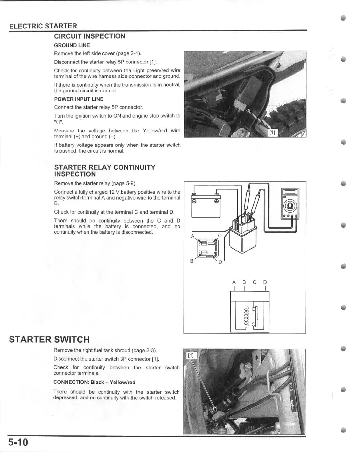
Disconnect the starter relay
5P
connector
11)
.
Check for continuity between
the
Light green/red wire
terminal
of
the
wire harness side connector and ground.
If
there is continuity when the transmission is in neutral,
the ground circuit is norma
l.
POWER
INPUT LINE
Connect the starter relay
5P
connector.
Tum
the ignition switch to
ON
and engine stop switch to
orr.
Measure the voltage between the Yellow/red wire
terminal (+)
and
ground
(-).
If
batter)' voltage appears only when t
he
starter switch
Is
pushed
,
the
circuit
is
normal.
STARTER RELAY CONTINUITY
INSPECTION
Remove the starter relay (page 5-9).
Connect a fully charged 12 V battery positive wire to the
relay switch terminal A and negative wire to
the
terminal
B.
Check
for
co
ntinuity
al
the
terminal C
and
terminal
O.
There should be continuity between the C and 0
terminals while the battery
is
connected. and no
continuity when
the
battery
is
disconnected.
STARTER SWITCH
5-10
Remove
the
right rueltank shroud (page 2-3).
Disconnect the starter switch 3P connector [1].
Check for continuity between the starter switch
connector terminals.
CONNECTION: Black - Yellow/red
There should
be continuity with the starter switch
depressed,
and
no
con
tinuity with the
swi
t
ch
re
leased.
~
..
r
~
~
to
(@
~
0."
I
A C /
T
=
B 0
~
~
~ ~
i
:1:
: 9