Installation - Fusing and Power Consumption
Fusion4 MSC-L Part No.: 4418309_Rev09
4 - 16 Installation & Operation Manual
Honeywell
4.6.1.2 External Fusing
External fuse can also be connected to the AC mains input available for
the MSC-L. There are two different power supply units, which can either
be powered using the individual AC sources or the common AC source.
Use two 217 005.P (little fuse) or equivalent on each AC source for a
system with separate AC mains for each power supply.
Use a single 217 010.P (little fuse) or equivalent for the common AC
source.
NOTE: External fusing is not required, as all the fusing is
done internally on the CAN-PSF-MSC board.
4.6.2 Power Consumption
The maximum consumed mains power depends on the external loads,
which can add up to 690 W.
The MSC-L contains DO-SSR-AC interfaces. The SSR relays are used
for switching AC signals connected to the MSC-L load.
The following boards in the MSC-L contain DO-SSR-AC interfaces.
1. CAN-ARM-MSC (one per backplane)
2. CAN-IN-OUT-MSC (two per backplane)
On each CAN-ARM-MSC board there are 12 SSR interfaces and on
each CAN-IN-OUT-MSC board there are four SSR interfaces.
Every DO-SSR-AC needs an optional fuse to protect the internal
electronics for the high current drawn. The 22 fuses are placed on the
optional MSC-SHORTCUT-BOARD. These fuses when placed on the
MSC-L protect the electronics against the high current condition.
For the MSC-SHORTCUT-BOARD board only the fuses are assembled
and not the 0E resistors. The MSC-SHORTCUT-BOARD board has 22
fuses, and the SSR output is connected to the MSC-L load through the
fuse. The MSC-SHORTCUT-BOARD is directly interfaced to the
backplane through the 48 pin connector.
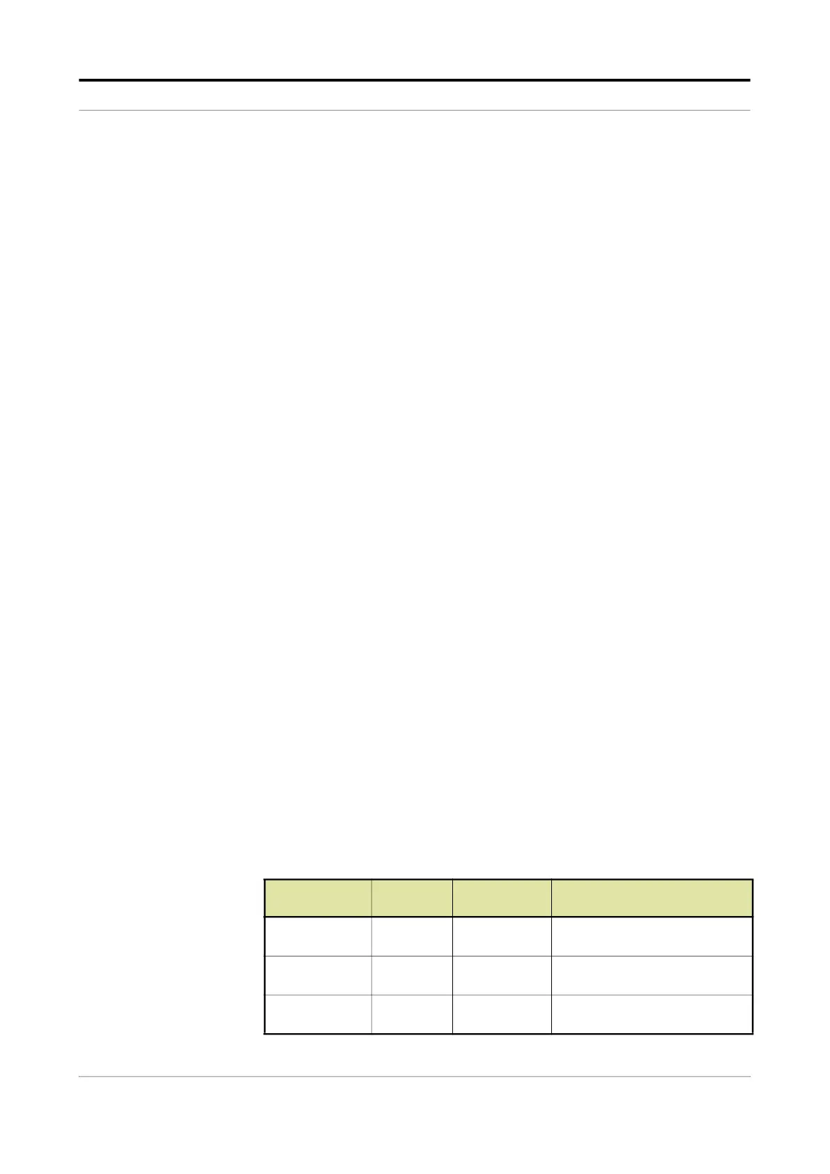
The following table provides an example of the maximum dissipation of
the boards, based on the specific main voltage conditions for the
particular region/country, for the site where the MSC-L is installed.
Boards
Number
of boards
Dissipation Description
CAN-ARM-MSC 2 15.4 W The dissipation is based on the
maximum load.
CAN-IN-OUT-
MSC
4 25 W The dissipation is based on the
maximum load.
CAN-HMI-MSC 1 7.2 W The dissipation is based on the
maximum load.

 Loading...


