Operation - System Configuration
Part No.: 4418309_Rev09 Fusion4 MSC-L
Honeywell Installation & Operation Manual 5 - 119
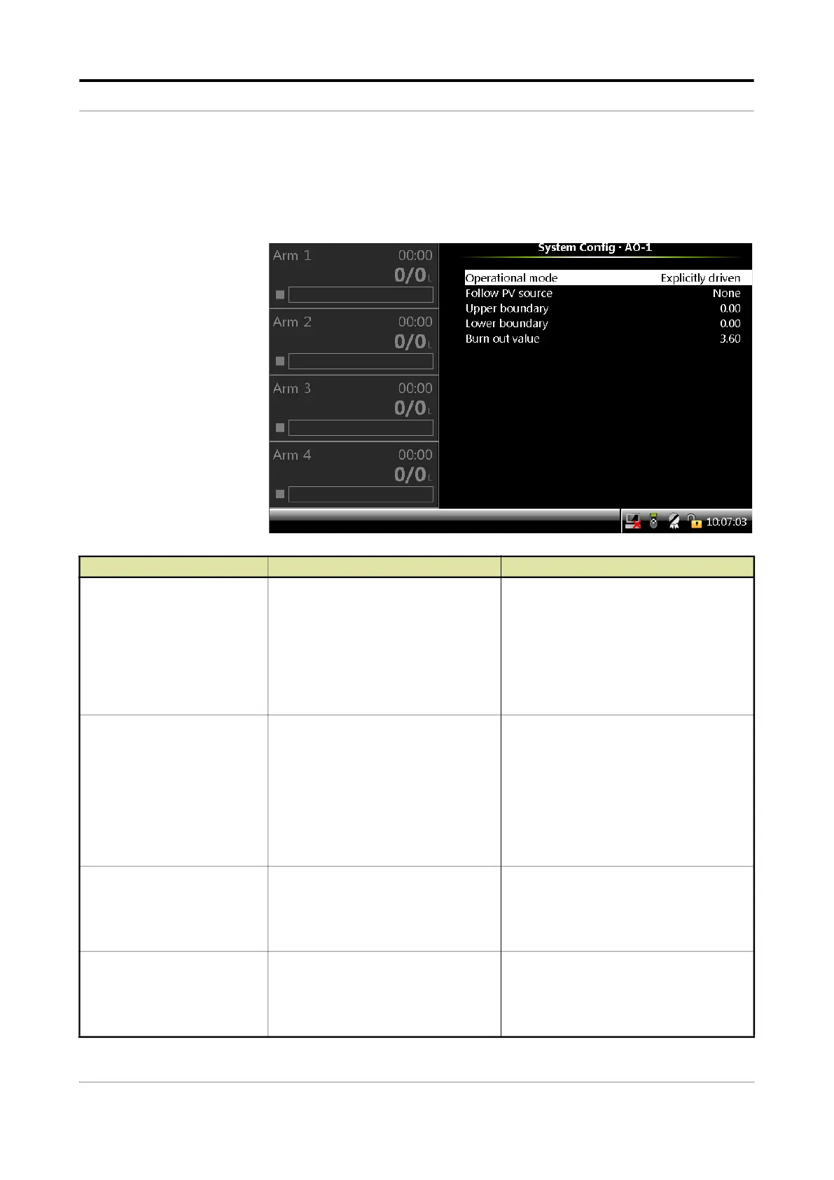
5.13.1.4.5 AO
On the System Config . Device . I/O Settings screen, select the
available Analog Outputs (AOs). The following entities are displayed on
the System Config . AO-n screen.
Entity Description Value range
[Operational mode]
With this entity you can select between
two modes for the analog output.
If AO is assigned to ACV valve type,
keep operational mode as
<Explicitly
driven>.
<Explicitly driven> (default)
- The output
value is set by the application (for
example, valve control).
<Follow PV> - The output reflects one of
the Primary Values measured by the
MSC-L.
<Calibrate Low>
<Calibrate High>
[Follow PV source]
With this entity you can select the
process variable to be mapped on the
analog output (4-20 mA).
<None> (default)
<Batch GOV>
<Batch GSV>
<Batch mass>
<Batch Flowrate>
<Batch instant. temp>
<Batch instant. pressure>
<Batch instant. density>
[Upper boundary]
With this entity you can select the PV
value at 20 mA.
For the actual current value linear
interpolation is used between
[Lower
boundary] and [Upper boundary].
default =
0.00
For units, see Value range of [PV address].
Note: The Upper boundary values are set
as per the units selected in the
[PV
address] entity.
[Lower boundary]
With this entity you can select the PV
value at 4 mA.
For the actual current value linear
interpolation is used between
[Lower
boundary]
and [Upper boundary].
default =
0.00
For units, see Value range of [PV address].
Note: The Lower boundary values are set
as per the units selected in the
[PV
address]
entity.
 Loading...


