Installation - Wiring Termination Guidance
Part No.: 4418309_Rev09 Fusion4 MSC-L
Honeywell Installation & Operation Manual 4 - 19
4.7.2 Backplane Boards
All the external wires of the MSC-L connect to one of the Phoenix
Contact connectors of the backplanes. These backplanes are mounted
on the rear of the MSC-L enclosure.
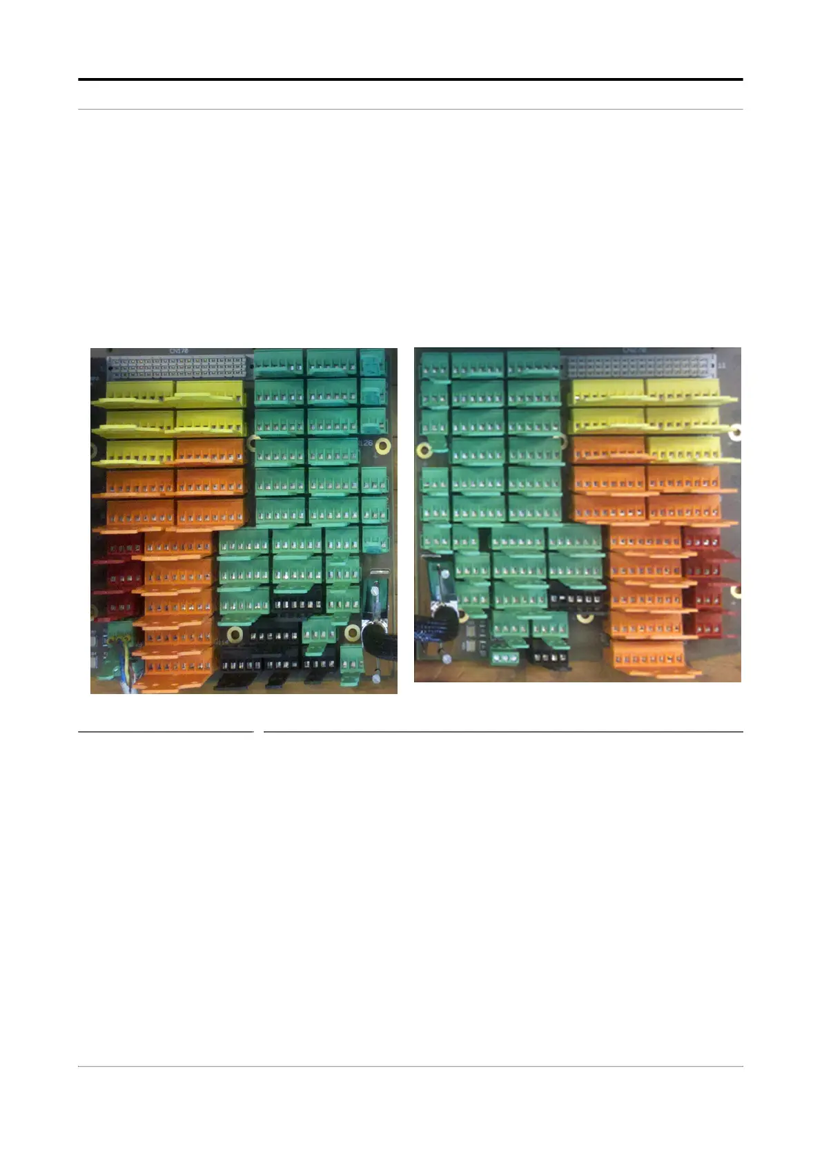
The backplane connectors have a unique CN number, color, and XY
coordinate. The connectors contain 3, 4, 5, 6, or 8 pins. ARM-1-
Backplane-MSC start with the CN number CN101 and contains 52
connectors. ARM-2-Backplane-MSC start with the CN number CN201
and contains 49 connectors.
FIGURE 4-7 Backplane boards

 Loading...


