System Description - PCB Layout
Part No.: 4418309_Rev09 Fusion4 MSC-L
Honeywell Installation & Operation Manual 3 - 31
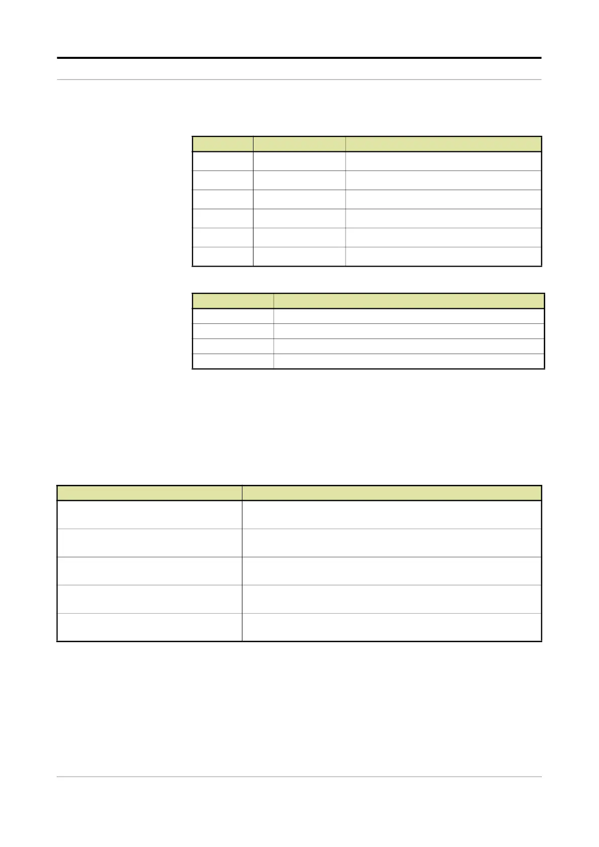
SW1 - FlexConn jumper function switches
JP7 and JP8 - Jumper for RS communication termination setting
3.6.1.3 CAN-IN-OUT-MSC
3.6.1.3.1 Functions
The function of the CAN-IN-OUT-MSC board is to provide I/O functions,
which are necessary to control the enhanced loading and additive
injection processes.
Following are the functions of the CAN-IN-OUT-MSC board.
Reference Jumper name Function when set to ON
SW1-1 FlexConn JP1 W&M entities protection
SW1-2 FlexConn JP2 Password is read protected
SW1-3 FlexConn JP3 Nothing is used
SW1-4 FlexConn JP4 Spare
SW1-5 FlexConn JP5 Spare
SW1-6 FlexConn JP6 CAN bus termination
Position Description
JP7 (1-2) Closed RS-485 communication terminated with 120 for COM Port 1 / 6
JP7 (2-3) Closed RS-485 communication NOT terminated for COM Port 1 / 6
JP8 (1-2) Closed RS-485 communication terminated with 120
for COM Port 2/ 7
JP8 (2-3) Closed RS-485 communication NOT terminated or COM Port 2/ 7
Function Description
3 Digital Input AC (DI-AC) circuits Converts high voltage switched AC signals into an isolated logic signal
that can be read by the FlexConn generic microprocessor.
15 Digital Input DC (DI-DC) circuits Converts switched DC signals into an isolated logic signal that can be
read by the FlexConn microcontroller.
Analog Output (AO) circuit Converts signals from the FlexConn microcontroller into scaled 4-20 mA
analog signals.
4 Digital Output Solid State Relay AC (DO-
SSR AC) circuits
Converts logic signals from the FlexConn generic microcontroller into
isolated, high voltage switched AC signals.
4 Digital Output Solid State Relay AC/DC
(DO-SSR) circuits
Converts logic signals from the FlexConn generic microcontroller to
switched high power AC or DC signals.

 Loading...


