Home
Honeywell
Desktop
Fusion4 MSC-L
Page 138 (4.7.6 Internal Wiring diagram)
Honeywell Fusion4 MSC-L - 4.7.6 Internal Wiring diagram; 4.7.6.1 AC Cable 1 (Gland 1)
531 pages
Manual
To Next Page
To Next Page
To Previous Page
To Previous Page
Loading...
Installation - Wi
ring T
ermination Guidance
Fusion4 MSC-L
Part No.: 4418309_Rev09
4 - 34
I
ns
tallation & Operation Manual
Honeywell
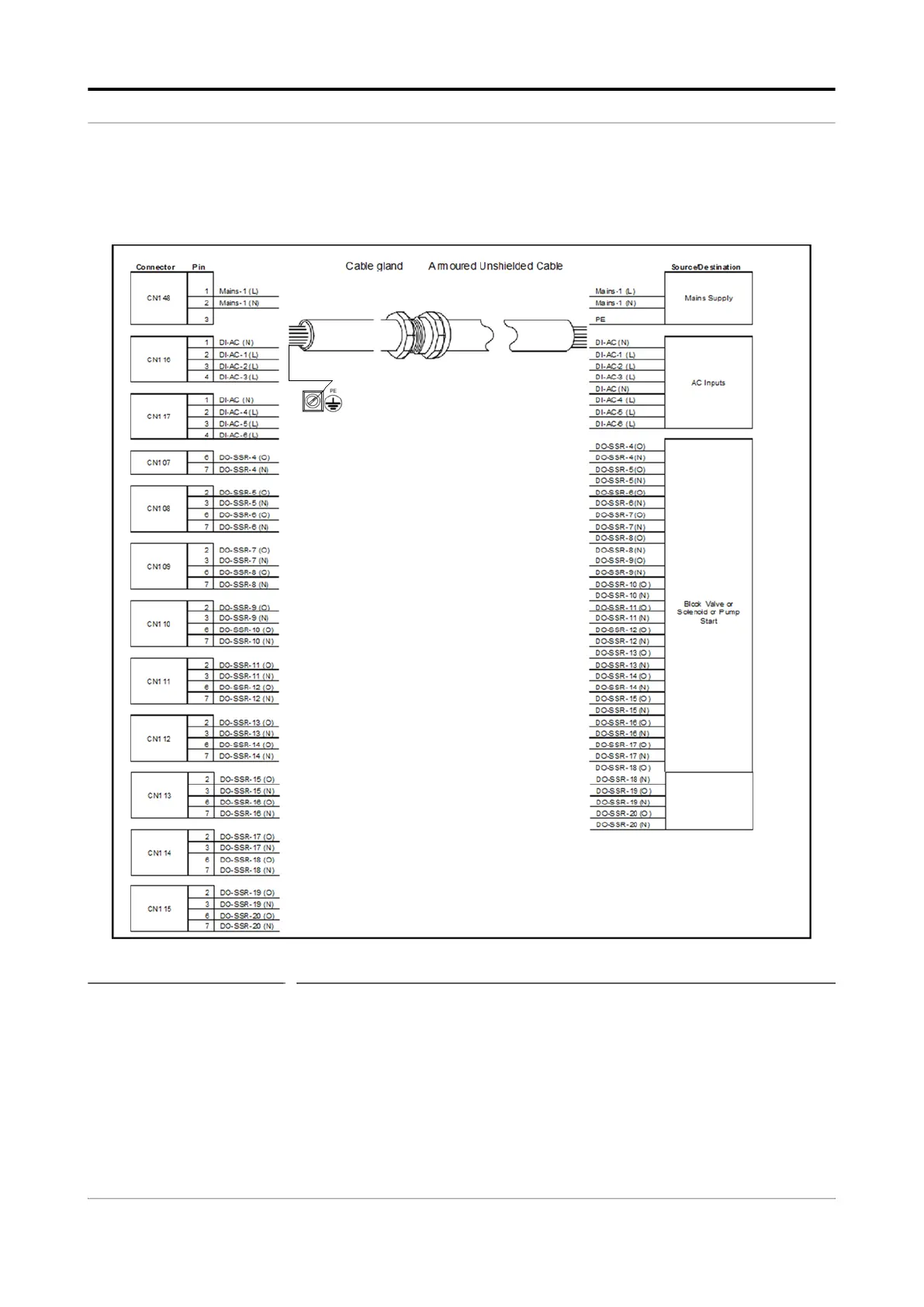
4.7.6
Internal Wiring diagram
4.7.6.1
AC Cable 1 (Gland 1)
FIGURE 4-12
AC cable 1 (gland 1)
137
139
Table of Contents
Main Page
FrontIOM
1
118-4418309-D09.pdf
3
CHAPTER 1 General
15
1.1 Product Overview
15
1.2 Functionality Overview
17
1.3 Target Audience for this Manual
17
CHAPTER 2 Safety
19
2.1 Safety Conventions
19
2.1.1 Warnings
19
2.1.2 Cautions
19
2.2 Safety Instructions for the MSC-L
20
2.2.1 General
20
2.2.1.1 EC Declaration of Conformity (for EU)
20
2.2.1.2 Control Drawings for FM & CSA
20
2.2.1.3 Users
21
2.2.1.4 Additional Information
21
2.2.1.5 Environmental Conditions
21
2.2.2 Operation
21
2.2.3 Maintenance and Troubleshooting
21
2.2.4 Personal Safety
21
2.2.4.1 General
22
2.2.4.1.1 Opening the MSC-L
22
2.2.5 Commissioning and Maintenance
22
2.2.5.1 Tools
22
2.2.6 Electrical
22
2.2.6.1 Grounding
22
2.2.7 Accordance to Regulations
24
2.2.7.1 Explosion Safety Limiting Values
24
2.2.7.2 Explosion Safety
24
2.2.7.3 Low-Voltage Directive
24
2.2.7.4 The MSC-L Labels
25
2.3 Safety Instructions for the LAD
26
2.3.1 General
28
2.3.1.1 EC declaration of conformity (for EU)
28
2.3.1.2 Control Drawings for FM & CSA
28
2.3.2 Explosion Safety
28
2.3.3 Commissioning
28
2.3.4 Operation
28
2.3.5 Maintenance and Troubleshooting
28
2.3.6 Additional Information
29
2.3.7 Environmental Conditions
29
2.3.8 The LAD Labels
30
2.4 Safety Instructions for the IR Controller
31
2.4.1 General
32
2.4.2 Precautions
32
2.4.2.1 EC declaration of conformity (for EU)
33
2.4.3 Installation
33
2.4.4 Commissioning
33
2.4.5 Operation
33
2.4.6 Maintenance and Troubleshooting
33
2.4.7 Additional Information
34
2.4.8 IR Controller Labels
34
2.5 Liability
35
CHAPTER 3 System Description
37
3.1 Introduction
37
3.1.1 General
37
3.1.1.1 Transactions and Batches
37
3.1.2 Batch principle
37
3.1.2.1 Batch Flow Stages
38
3.1.3 Types of Blending
39
3.1.3.1 Straight Loading
39
3.1.3.2 Ratio Blending
39
3.1.3.3 Side Stream Blending
39
3.1.3.4 Sequential Blending
40
3.1.4 Additive Injection
41
3.1.5 Loading Principle
41
3.1.5.1 Device loading capabilities
43
3.1.6 Menu-based MSC-L Control
44
3.2 MID Compliance
44
3.2.1 Introduction
44
3.2.2 MID Approval Approach
44
3.2.3 Component-level Requirements
45
3.2.4 System-level Requirements
48
3.2.5 The Fusion4 MSC-L
48
3.3 System Architecture
49
3.4 FlexConn Modules
51
3.4.1 General
51
3.5 Hardware Structure
52
3.5.1 Housing
52
3.5.2 Interior
54
3.5.3 Grounding Concept
55
3.6 PCB Layout
59
3.6.1 PCB Details
60
3.6.1.1 CAN-HMI-MSC
60
3.6.1.1.1 Functions
60
3.6.1.1.2 Component Locations
62
3.6.1.2 CAN-ARM-MSC
64
3.6.1.2.1 Functions
64
3.6.1.2.2 Component Locations
66
3.6.1.3 CAN-IN-OUT-MSC
67
3.6.1.3.1 Functions
67
3.6.1.3.2 Component Locations
69
3.6.2 CAN-PSF-MSC
70
3.6.2.1 Functions
70
3.6.2.2 Power Board Connection
71
3.6.2.3 Hardware Specifications
71
3.6.2.4 Fuse Boards
73
3.6.2.4.1 MSC-SHORTCUT-BOARD
73
3.6.3 Device Electrical Features
73
3.6.4 System
73
3.6.5 Environment
74
3.7 Available Input/Output Functions of the MSC-L
74
3.8 Input Functions
76
3.8.1 General
76
3.8.2 Digital Input DC (DI DC)
76
3.8.2.1 Functional Description
76
3.8.2.2 Characteristics
78
3.8.3 Single Pulse Input
78
3.8.3.1 Functional Description
78
3.8.3.2 Characteristics
80
3.8.4 Dual-Pulse Input (Quad PI)
80
3.8.4.1 Functional Description
80
3.8.4.2 Characteristics
82
3.8.5 Analog Input (AI)
82
3.8.5.1 Functional Description
82
3.8.5.2 Characteristics
84
3.8.6 Resistance Temperature Detector
84
3.8.6.1 Functional Description
84
3.8.6.2 Characteristics
86
3.8.7 Digital Input AC (DI AC)
86
3.8.7.1 Functional Description
86
3.8.7.2 Characteristics
87
3.9 Output Functions
88
3.9.1 General
88
3.9.2 Pulse Output (PO DC)
88
3.9.2.1 Functional Description
88
3.9.2.2 Characteristics
90
3.9.3 Analog Output
90
3.9.3.1 Functional Description
90
3.9.3.2 Characteristics
91
3.9.4 Digital Output Electromechanical Relay (DC)
91
3.9.4.1 Functional Description
91
3.9.4.2 Characteristics
92
3.9.5 Digital Output Electromechanical Relay (AC or DC)
93
3.9.5.1 Functional Description
93
3.9.5.2 Characteristics
95
3.9.6 Digital Output Solid State Relay AC
95
3.9.6.1 Functional Description
95
3.9.6.2 Characteristics
97
3.10 Communication Functions
98
3.10.1 General
98
3.10.2 RS-485 Communication (2-wire or 4-wire)
98
3.10.2.1 Functional Description
98
3.10.2.2 Characteristics
100
3.10.2.3 Cable Specifications
100
3.10.3 Ethernet Communication
100
3.10.3.1 Functional Description
100
3.10.3.2 Characteristics
101
3.10.3.3 Cable Specifications
101
3.11 Security Guidelines
102
3.11.1 Device Security Recommendations
102
3.11.2 Network and security control Recommendations
102
3.11.3 How to report a security vulnerability
102
CHAPTER 4 Installation
105
4.1 Mounting and Dimensions
105
4.2 Gland Entries
110
4.2.1 General
110
4.2.2 Metric Gland Entries
110
4.2.3 NPT Cable Entries
111
4.3 Opening the MSC-L
112
4.4 Closing the MSC Lid
115
4.5 Removing/Replacing the PCBs
116
4.6 Fusing and Power Consumption
117
4.6.1 Fusing
117
4.6.1.1 Internal Fusing
117
4.6.1.2 External Fusing
120
4.6.2 Power Consumption
120
4.6.3 Disconnecting/breaker device
121
4.7 Wiring Termination Guidance
121
4.7.1 Wiring Architecture
121
4.7.2 Backplane Boards
123
4.7.2.1 ARM-1-BACKPLANE-MSC
124
4.7.2.2 Floorplan
125
4.7.2.3 Connector Overview
126
4.7.2.4 ARM-2-BACKPLANE-MSC
130
4.7.2.5 Floorplan
131
4.7.2.6 Connector Overview
132
4.7.3 General
136
4.7.3.1 Wire Sizes and Types
136
4.7.4 Recommended Cables
137
4.7.5 Wire Crimps
137
4.7.6 Internal Wiring diagram
138
4.7.6.1 AC Cable 1 (Gland 1)
138
4.7.6.2 AC Cable 2 (Gland 2)
139
4.7.6.3 DC cable 1 (Gland 3)
139
4.7.6.4 AC Cable 3 (Gland 4)
140
4.7.6.5 AC Cable 4 (Gland 5)
140
4.7.6.6 Analog Cable 1 (Gland 6)
141
4.7.6.7 AC Cable 5 (Gland 7)
142
4.7.6.8 DC Cable 2 (Gland 8)
142
4.7.6.9 DC Cable 3 (Gland 9)
143
4.7.6.10 DC Cable 4 (Gland 10)
144
4.7.6.11 DC Cable 5 (Gland 11)
144
4.7.6.12 Comms Cable 1 (Gland 12)
145
4.7.6.13 DC Cable 6 (Gland 13)
145
4.7.6.14 DC Cable 7 (Gland 14)
146
4.7.6.15 Comms Cable 2 (Gland 15)
146
4.7.6.16 DC Cable 8 (Gland 16)
146
4.7.6.17 DC Cable 9 (Gland 17)
147
4.7.6.18 AC Cable 6 (Gland 18)
147
4.7.6.19 DC Cable 10 (Gland 19)
147
4.7.6.20 DC Cable 11 (Gland 20)
148
4.7.6.21 AC Cable 7 (Gland 21)
149
4.7.6.22 AC Cable 8 (Gland 22)
149
4.7.6.23 Analog Cable 2 (Gland 23)
150
4.7.6.24 AC Cable 9 (Gland 24)
151
4.7.6.25 AC Cable 10 (Gland 25)
152
4.7.6.26 DC Cable 12 (Gland 26)
153
4.7.7 Connecting MSC-L to NexWatch DR4208S Card Reader
153
4.7.8 ARM-1-BACKPLANE-MSC Terminal Assignment Guide
153
4.7.9 ARM-2-BACKPLANE-MSC Terminal Assignment Guide
173
CHAPTER 5 Operation
189
5.1 General
189
5.1.1 Introduction
189
5.1.2 Text Conventions
189
5.2 Service Interfaces
189
5.3 Service Tools
190
5.3.1 Fusion4 IR Controller
190
5.3.2 Fusion4 Local Access Device
191
5.3.2.1 General
191
5.3.2.2 LAD Application Overview
193
5.3.3 Integrated Keyboard
194
5.3.4 Navigation with Fusion4 IR Controller and Fusion4 LAD
197
5.3.4.1 Basic Navigation (Fusion4 IR Controller + Fusion4 LAD)
197
5.3.4.2 LEDs (Fusion4 IR Controller + Fusion4 LAD)
198
5.3.4.3 Special Function Key (Only LAD)
199
5.3.4.4 SD Card
199
5.3.4.4.1 Product Type Selection
200
5.3.4.4.2 Directory Structure and File Organization
202
5.3.4.4.3 Guidelines
202
5.3.4.5 Language Packs
203
5.3.4.5.1 Building a Local Language Pack for the MSC-L
203
5.3.4.5.2 Configuring a User Display Language for the MSC-L
203
5.4 Menu and Navigation
203
5.4.1 General
203
5.4.2 Key benefits of the HMI on the Main Menu
204
5.4.3 Navigation Rules for the Menu-based Screens
204
5.4.4 Main Menu
204
5.4.5 Stream Selection
205
5.4.5.1 Product Streams
205
5.4.5.2 Additive Streams
206
5.4.5.3 External Additive Streams
207
5.4.6 Arm Selection
208
5.4.7 Text Input Screen
209
5.4.8 Numeric Input Screen
210
5.4.9 Enumeration Input Screen
210
5.4.10 Status Bar
211
5.5 Device Security
212
5.5.1 Security Levels (SL)
213
5.5.2 Rules of Navigation
213
5.6 Device Commissioning
215
5.6.1 Using the Menu
215
5.6.2 Menu Structure
215
5.6.2.1 System Configuration
217
5.6.2.2 Stream Configuration
223
5.6.2.3 Arm Configuration
230
5.6.2.4 Calibration
232
5.6.2.5 Info (Device Information)
234
5.6.2.6 Diagnostics
235
5.6.2.7 Transfer
240
5.6.2.8 LAD Functions
241
5.7 Loading Application Overview
242
5.8 Unloading Application Overview
243
5.9 LPG Loading Application Overview
246
5.10 Dual Bay Loading Application Overview
250
5.10.1 About Dual Bay Loading
250
5.10.2 MSC-L Licenses
251
5.10.3 Dual Bay Loading using MSC-L
251
5.10.4 Authorization Modes supported for Dual Bay Loading
252
5.10.5 Dual Bay Configuration
252
5.10.6 Dual Bay Loading Operations
260
5.11 Interfacing With External Additive Controller
266
5.11.1 Connecting External Additive Controllers
267
5.11.1.1 Topology and Wiring
267
5.11.2 Configuring External Additive Controller
268
5.11.2.1 Device Configuration - Communication
268
5.11.2.2 Stream Configuration
269
5.11.2.3 Stream Configuration - Stream n
269
5.11.2.3.1 Stream Configuration - Stream n - Identification
269
5.11.2.3.2 Stream Configuration - Stream n - I/O Bindings
270
5.11.2.3.3 Stream Configuration - Stream n - Control Settings
270
5.11.2.3.4 Stream Configuration - Stream n - Alarms
271
5.11.3 Configuring MSC-L
271
5.11.3.1 System Configuration
271
5.11.3.2 External Additive Stream Configuration
272
5.11.3.3 Arm Configuration
272
5.11.4 Loading
273
5.11.4.1 Process Data
274
5.11.4.2 Transaction Details
276
5.11.4.3 Alarm Handling for External additive streams
277
5.11.4.3.1 Setting Alarm Actions
277
5.11.4.3.2 External Additive Alarms Generated by MSC-L
278
5.11.4.3.3 Mapping of Alarms on External Additive Controller
278
5.12 Sequential Blending Overview
279
5.12.1 Configuration
280
5.12.2 Load Order
281
5.12.3 Inter mini batch behavior
281
5.12.4 Flow Profile
282
5.12.5 Batch record
282
5.12.6 Alarms
282
5.12.7 Calibration
282
5.13 System Configuration
283
5.13.1 Device Configuration
284
5.13.1.1 Device Configuration . General
284
5.13.1.1.1 System Config . General Identification
285
5.13.1.1.2 System Config . General . Units
285
5.13.1.1.3 System Config . General . Display
287
5.13.1.1.4 System Config . General . Time
291
5.13.1.1.5 System Config . Device . Settings
291
5.13.1.2 System Config . Device . I/O Binding
293
5.13.1.2.1 System Config . I/O bindings . Inputs
293
5.13.1.2.2 System Config . I/O bindings . Outputs
293
5.13.1.3 System Config . Device . Communication
293
5.13.1.3.1 Serial
294
5.13.1.3.2 Ethernet
297
5.13.1.3.3 IR HHC
298
5.13.1.4 System Config . Device. I/O Settings
298
5.13.1.4.1 DI (for both AC# and DC#)
300
5.13.1.4.2 PI
301
5.13.1.4.3 RTD
303
5.13.1.4.4 AI
305
5.13.1.4.5 AO
307
5.13.1.4.6 PO
308
5.13.1.4.7 EMR
309
5.13.1.5 System Config . Device . Alarms
309
5.13.1.5.1 System Config . Alarms . Next scheduled service
310
5.13.1.5.2 System Config . Alarms . Programmable Alarms
310
5.13.1.5.3 System Config . Alarms . Deadman
311
5.13.1.5.4 System Config . Alarms . Permissives
313
5.13.1.5.5 System Config . Alarms . Fixed
314
5.13.1.6 System Config . Device . Authorization
314
5.13.1.6.1 System Config . Authorization. Setup
315
5.13.1.6.2 System Config . Authorization. Databases
316
5.13.1.7 Device Configuration . Base Conditions
318
5.13.1.8 Device Configuration . Workflow Settings
319
5.13.1.8.1 System Config . Options
320
5.13.1.8.2 System Config . Prompts
323
5.13.1.9 Device Configuration . RIT Panel
323
5.13.2 Bay Configuration
325
5.13.2.1 System Config . bay . Identification
325
5.13.2.2 Bay Configuration . I/O Binding
326
5.13.2.2.1 Bay Configuration . I/O Binding . Inputs
326
5.13.2.2.2 Device Configuration . I/O Binding . Outputs
327
5.13.2.3 Bay Configuration . Alarms
327
5.13.2.3.1 System Config . Alarms . Programmable alarms
328
5.13.2.4 System Config . Bay . Permissives
329
5.14 Stream Configuration
331
5.14.1 Stream Configuration - Product Streams
332
5.14.1.1 Stream Config. . Stream n . Identification
332
5.14.1.2 Stream Config . Stream n . I/O Bindings
333
5.14.1.2.1 The I/O Bindings . Input Parameters
334
5.14.1.2.2 The I/O Bindings . Output Parameters
336
5.14.1.3 Stream Config. . Stream n . Control Settings
337
5.14.1.3.1 Product Control
337
5.14.1.3.2 Valve Control
339
5.14.1.4 Volume Conversion
340
5.14.1.4.1 Volume Conversion Essential Information
340
5.14.1.4.2 Volume Conversion Calculation Details
345
5.14.1.4.3 Stream Config. Stream n . Volume Conversion
350
5.14.1.5 Stream Config . Stream n . Alarms
352
5.14.2 Stream Configuration . Additive streams
362
5.14.2.1 Additive Stream Config. . Stream n . Identification
363
5.14.2.2 Additive Config. Stream n . I/O Bindings
363
5.14.2.2.1 The I/O Bindings . Input Parameters
364
5.14.2.2.2 The I/O Bindings . Output Parameters
366
5.14.2.3 Additive Stream Config. . Stream n . Control Settings
368
5.14.2.3.1 Additive Control
368
5.14.2.3.2 Solenoid
369
5.14.2.4 Additive Stream Config. Stream n . Alarms
370
5.14.2.4.1 Leaking Valve
370
5.14.2.4.2 No Additive
371
5.14.2.4.3 No Pump
371
5.14.2.4.4 Block Valve Fault
372
5.14.2.4.5 Deviation
372
5.14.2.4.6 Fixed
373
5.14.3 Stream Configuration - External Additive streams
374
5.14.3.1 Stream Config - Ext add n - Identification
376
5.14.3.2 Stream Config - Ext add n - Alarms
377
5.15 Arm Configuration
381
5.15.1 Arm Configuration . Arm n . Identification
382
5.15.2 Arm Configuration . Arm n . I/O Bindings
382
5.15.2.1 The I/O Bindings . Input Parameters
382
5.15.2.2 The I/O Bindings . Output Parameters
383
5.15.3 Arm Configuration . Arm n . Control Settings
384
5.15.4 Arm Configuration . Arm n . Product Streams
386
5.15.5 Arm Configuration . Arm n . Additive Streams
388
5.15.6 Arm Configuration . Arm n . External Additive Streams
389
5.15.7 Arm Configuration . Arm n . Recipes
390
5.15.8 Arm Configuration . Arm n . Alarms
395
5.15.8.1 Flow Rate
397
5.15.8.1.1 Initial Flow . Alarms
397
5.15.8.1.2 Full Flow . Alarms
397
5.15.8.1.3 Pre-stop Flow . Alarms
398
5.15.8.2 Programmable Alarms
398
5.15.8.3 Block Valve Fault
400
5.15.8.4 Preset Overrrun
400
5.15.8.5 Clean Arm Underrun
401
5.15.8.6 Stop Switch not covered
401
5.15.8.7 Fixed
401
5.16 Logs
401
5.16.1 Transaction
403
5.16.2 Calibration
408
5.16.3 Alarm
410
5.16.4 Events
410
5.16.5 Load Profiles
411
5.17 Diagnostics
412
5.17.1 Alarms
414
5.17.2 Dashboard
414
5.17.2.0.1 Dashboard I/O Type Symbols
415
5.17.2.0.2 Digital Input
416
5.17.2.1 Digital Output
416
5.17.2.2 Pulse Input
417
5.17.2.3 Pulse Output
417
5.17.2.4 Analog I/O
418
5.17.3 System Health
418
5.17.4 Process Data
420
5.17.5 Storage Info
421
5.17.6 Accumulated Totals
421
5.17.7 Comms Info
429
5.17.8 Device Tasks
430
5.17.8.1 Reset Tasks
431
5.17.8.2 Execute Tasks
432
5.17.8.3 Clear Tasks
433
5.17.9 Maintenance
435
5.17.10 Advanced
437
5.18 Calibration
440
5.18.1 Why Calibrate?
440
5.18.2 Calibration Menu Choice
443
5.18.3 Manual Calibration
444
5.18.3.1 Product Stream Selection
445
5.18.3.2 Additive Stream Selection
449
5.18.4 Wizard Calibration
452
5.18.4.1 Product Stream Selection
453
5.18.4.2 Additive Stream Selection
460
5.19 Info (Device Information)
465
5.19.1 Device Information
465
5.19.2 Status Legend
468
5.20 Transfer
469
5.20.1 General
470
5.20.2 Retrieving Transaction Records
471
5.20.2.1 Transaction Details
473
5.20.3 Configurations
476
5.20.4 Events / Logs
476
5.20.5 Calibration Records
477
5.20.6 Recipes
478
5.20.7 Language Packs
478
5.21 LAD Functions
481
5.21.1 General
481
5.21.2 Firmware Update
482
5.21.2.1 Verify the Firmware Update
484
5.21.3 Test LED and LAD Information Submenus
485
5.21.4 Function Key
486
5.21.5 LAD Information
486
5.21.6 Format SD Card
487
5.22 Truck Driver Operations
488
5.22.1 Overview
488
5.22.2 Default standalone MSC-L workflow
489
5.22.3 STOP Key Operations
498
5.22.4 Error Scenarios
501
5.22.4.1 Invalid Pin
501
5.22.4.2 Invalid Preset
501
5.22.4.3 Batch not Feasible
502
5.22.4.4 Batch stopped due to an Alarm
502
5.23 Service Technician Operations
503
5.23.1 Configuration Options
503
5.23.2 Configuration Order
504
5.23.3 Configuration File
505
5.23.4 Recipe Transfer using the Fusion4 LAD
506
5.24 Running Screens
506
5.24.1 Loading Progress
506
5.24.2 Left Arm Pane
509
5.25 Recovery Mode
509
5.26 W&M Compliance
510
5.26.1 W&M Intended
510
5.26.2 W&M Sealing
510
5.26.3 Device Health
512
5.26.4 MSC-L W&M compliance
512
CHAPTER 6 Alarm Handling
513
6.1 General
513
6.2 Basic Concepts
513
6.2.1 Alarm Name
513
6.2.2 Alarm Scope
513
6.2.3 Alarm State
514
6.2.4 Alarm Action
514
6.2.5 Date & Time
515
6.3 Alarm Severity
515
6.3.1 Setup
515
6.3.2 Configuration
515
6.3.3 Scenario
515
6.4 Alarm Output Configuration
517
6.5 Operations on alarms
518
6.5.1 Raising
518
6.5.2 Clearing
518
6.5.3 Resetting
518
6.5.4 Acknowledging
518
6.5.5 Resetting all alarms
519
6.5.6 Acknowledging all alarms
519
6.6 Active Alarms
520
6.7 Alarm Logs
521
6.8 List of all alarms
521
6.8.1 Device Alarms
521
6.8.2 Bay Alarms
522
6.8.3 Arm Alarms
523
6.8.4 Product Stream Alarms
524
6.8.5 Additive Stream Alarms
527
6.8.6 External Additive Stream Alarms
529
6.8.7 Dual Bay Alarms
530
F4IOM_Lastpage
531
Untitled
531
Related product manuals
Honeywell enCore FC1
133 pages
Honeywell enCore FC Series
133 pages
Honeywell Esser 8010
78 pages
Honeywell 200 Series
100 pages
Honeywell 400 Series
108 pages
Honeywell VX6
48 pages
Honeywell T5810XL
99 pages
Honeywell Thor VX8
44 pages