The following figures and explanations are only examples, further information and the actual set-
up takes place using the Configuration and analysis software enSuite.
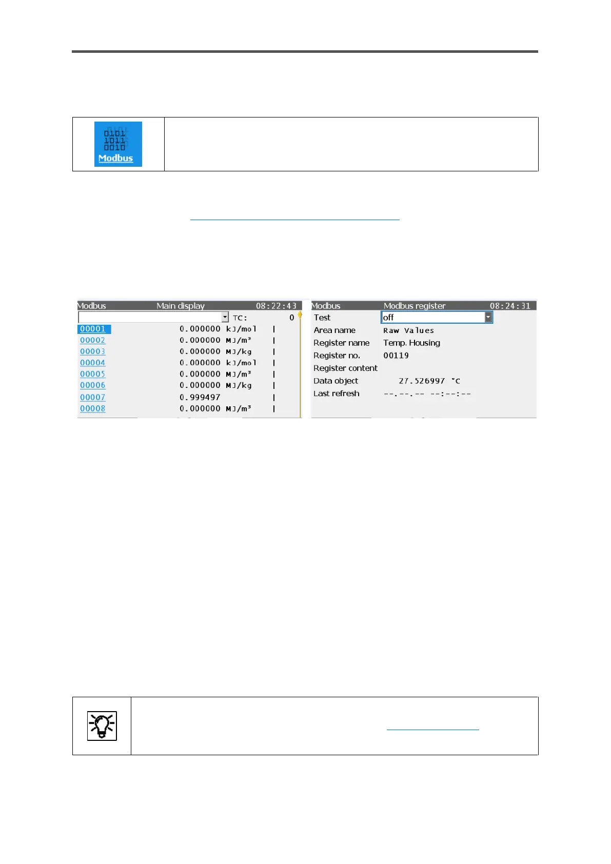
The main display provides an overview of all the parameterized Modbus areas of the enCore device
in the first line. If there are no different areas parameterized (as in this example), the list will be
empty. All the registers (for the selected area) will be listed in ascending order. As an option, you can
open a detailed display for any register using the number displayed as a link (first column).
Figure 7.51: Example of Modbus displays
The second column on the main display shows the register content. The telegram counter TC at the
top right of the screen counts the number of telegrams transferred. A symbol – | (vertical line) in the
example – indicates for each import or export tab that the data in this register have been transferred
successfully. Using the symbols – (dash), \ (backslash), | (vertical line) and / (slash), a sort of rotary
hub is simulated which changes by one step each time when the individual register has been
transferred successfully.
The following information is provided in the detailed Modbus register display:
Test on/off: Test function of the selected export register enabled/disabled
Area name: Name of the register section (parameter name)
Register name: Name of the register (parameter name)
Register number: Register number of the import or export register
Register content: Transferred value (hexadecimal)
Data object: Transferred value, formatted with unit
Last refresh: Date and time
 Loading...