STRUCTURE AND INSCRIPTIONS OF THE GASLAB Q2
Information for general use
Rev. M / 73023639
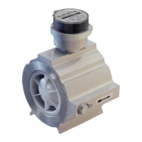
Apart from the type labeles, there is still engraved information on the device. Next to the flow meters
there are setting marks for the gas flow rates.
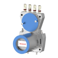
Arrows at the inlet and outlet indicate the direction of the gas flow. Above the gas inlets, the
maximum inlet pressures are also indicated, which must not be exceeded under any circumstances.
On the underside of the device there is the designation GROUND for the electrical connection to the
equipotential bonding system and earth.
These specifications must also always be observed!
Setting marks for the gas flow rates
Arrows for the direction of gas flow
Maximum inlet pressure process gas
Maximum inlet pressure Calibration gas
Potential equalization connection point (PA)
Figure 3.7 Engraved device Information
3.5. Explanation of explosion protection markings
Designations around these symbols (on the nameplate) indicate the area
of application taking explosion protection into account.
Notified body, device group, device category, Ex zone, Ex class, type of
protection, explosion group, temperature class and device protection level
are indicated among other things.
Description / Explanation
Ex marking for Notified Body
Notified Bodies
are state notified and supervised testing bodies. On behalf of the manufacturer, they
inspect the conformity or compliance with corresponding standards and regulations for
his products and or his production.
 Loading...