4.2. Measuring point overview
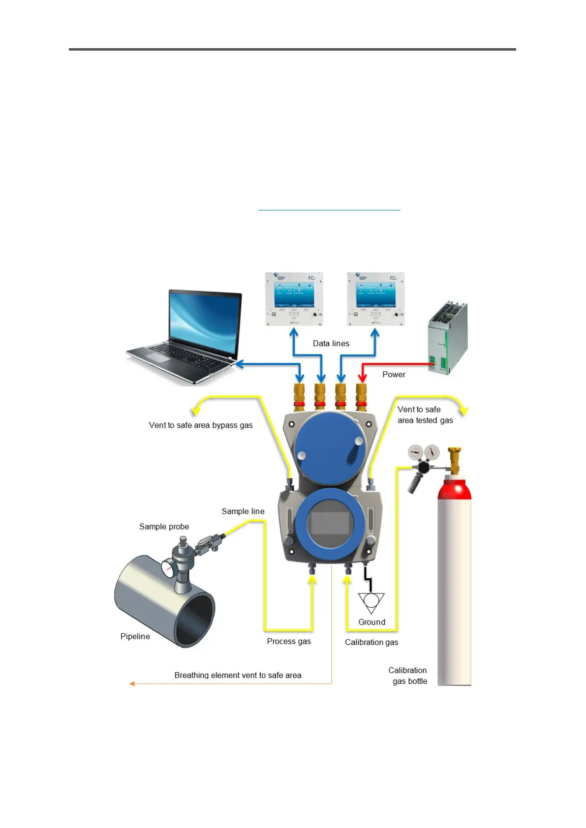
A typical measurement point consists of a sampling line from the gas pipeline to the measurement
device. The stream of gas is measured quickly and continuously and then fed into the vent (waste)
gas. If the pipeline pressure is higher than the maximum inlet pressure of the GasLab Q2, a pressure
reduction system must be installed and adjusted upstream of the process gas inlet.
The operational calibration gas mixture is generally supplied using a gas cylinder with a pressure
reducer near the GasLab Q2 and ensures that the measuring accuracy is maintained. The gas in a
10 l ≙ 0.01 m
3
≙ 0.353 cft cylinder will suffice for several years of operation. The vent (waste) gas line
should be routed separately, see section 5.3.2 Connect the vent gas line for details. In general, all
pipes and components should be permanently installed. The power supply and the communication
cables must be connected and installed as usual in industrial environments. The following diagram
shows a typical system layout:
Figure 4.3: System overview
 Loading...