The physical measurement is carried out in the instrumentation section with the aid of a sensor
block containing the electronics for the complete control, regulation, measurement acquisition and
transmission.
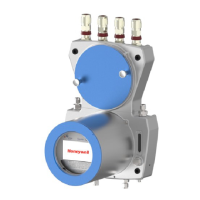
A two-channel double block and bleed valve block (DBB) supplies the gases to the sensor block.
Each gas channel is shut off by 2 solenoid valves. There is ventilation between the valves. This DBB
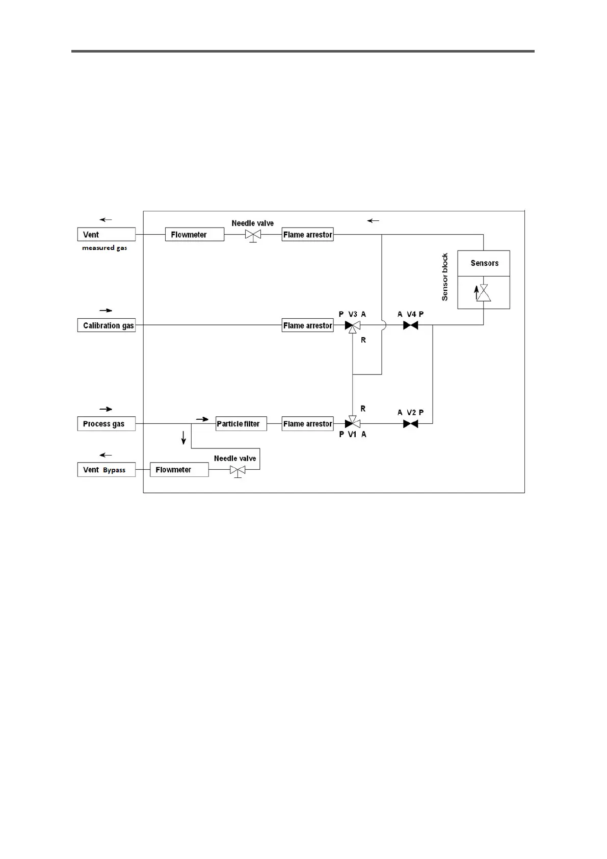
technology prevents the supplied gases mixing, even if the valves leak. The figure shows a layout of
the gas routes. The arrows indicate the flow direction of the gas.
Figure 4.2: Gas routes in the device
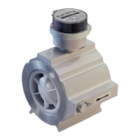
The sensor block consists of parts with gas channels as well as the electronics and sensors. An
integral pressure regulator reduces the inlet pressure for measurement. The measuring system
typically operates at a gauge pressure of around 16 KPa ≙ 2.32 psi ≙ 160 mbar. The gas is then supplied
to the actual sensor chamber. The infrared sensor and the thermal conductivity sensor analyze the
gas there and a pressure transmitter measures the gas pressure.
The block is heated electrically to 70°C ≙ 158°F ≙ 343K to ensure stable results. An installed fan
prevents the temperature from rising too high. A temperature sensor records this block temperature,
which is called TSB.
After the measurement the gas is led back into the lower part of the housing. The typical flow rate is
between 1.059ft
3
/h to 2.118 ft
3
/h ≙ 0.03 m
3
/h to 0.06 m
3
/h ≙ 30 l/h to 60 l/h. The flow rate may be changed
depending on the application.
 Loading...