GASLAB Q2 AFTER DELIVERY AND AT THE PLACE OF USE
Information for general use
Rev. M / 73023639
5.3.1. Fluid interfaces
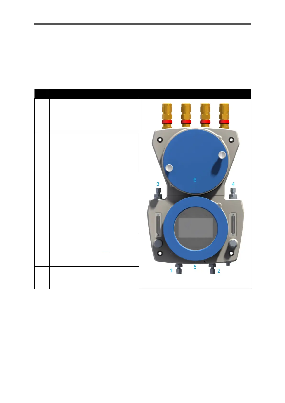
GasLab Q2 has 2 gas inlets and two gas outlets, each of which is protected by a flame arrester. Two
breathing points are used to enable atmospheric pressure equalisation between the inside of the
device and the environment.
An overview of all gas inlets and breathing elements is shown in the following figure:
Process gas (PG) with integral particle
filter to act as a frit in the gland
Inlet pressure (gauge):
from 0.15MPa ≙ 21.76psi ≙ 1.5bar
to 0.3 MPa ≙ 43.51psi ≙ 3bar
Calibration gas cylinder (CAL)
Operational calibration gas (CH
4
+
CO
2
)
Inlet pressure (gauge):
from 0.15MPa ≙ 21.76psi ≙ 1.5bar
to 0.25MPa ≙ 36.26psi ≙ 2.5bar
Outlet from integrated bypass
Flow rate up to around
300 l/h ≙ 0.3 m
3
/h ≙ 10.59ft
3
/h
(if necessary)
Outlet from sensor path
Typical flow rate
1.059ft3/h ≙0.03m
3
/h ≙30l/h
Max. flow rate
2.118ft3/h ≙ 0.06m
3
/h ≙ 60l/h h
Main breather with
¼" NPT connection thread for pipelines
as described in section 2.6. If a pipe-
line is connected, it must be separate
from all other vent (waste) gas lines.
Auxiliary breathers (on the reverse)
Pipeline connection
not possible and not required
Figure 5.2: Definition of fluid connections
The gas connections are always equipped by the manufacturer in the standard version with 6 mm
Swagelok pipe screw unions. Alternatively, ¼ " is possible.
The process gas connection (bottom left) has an internal particle filter, which serves only as device
protection and is not a replacement for a primary filtration system. The right gas inlet is used to
connect the operating calibration gas or particle-free test gases.
The inlet pressure must not exceed the engraved maximum pressure at any inlet
 Loading...