POSSIBLE MALFUNCTIONS AND TROUBLESHOOTING
Information for general use
Rev. M / 73023639
Action: Checking the communication links
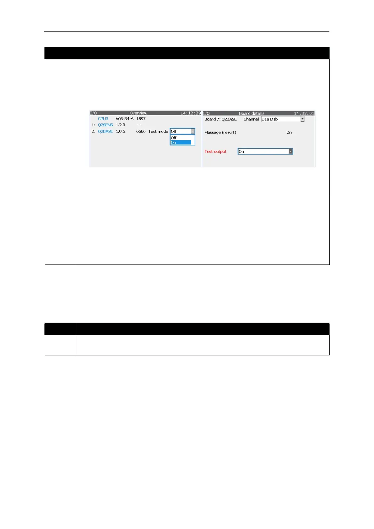
Navigate to the I/O overview display. Select “On” for the test mode of the appropriate
hyperlink (Q2Base in the example). Click on the hyperlink to go to the Board details sub-
display. Requirement: The inputs and outputs being tested are parameterized, the
device is installed, sealed and ready for operation.
You are logged in with the required rights.
Figure 9.1: I/O overview and Board details displays
Select the output you wish to test under “Channel” in Board details. The desired state of
the output is shown next to “Message (result)”. In the example, it is “On”.
You can change the states of the output, regardless of the actual conditions, using “Test
output”. Measure each output in both states (On/Off) to obtain a complete overview of
the error situation.
Use a measurement device to test whether a connection exists, will be created or has
been interrupted between the switch signal cable and the return cable.
Do not forget to switch off test mode again.
Rectification of the errors under point 7 (Sensor error)
Action: Checking the sensors
If there are entries in red text in the “Sensor values” display, despite the parameter set not
having been changed, a defect has occurred which you cannot rectify. Contact Honeywell.
 Loading...