STRUCTURE AND INSCRIPTIONS OF THE GASLAB Q2
Information for general use
Rev. M / 73023639
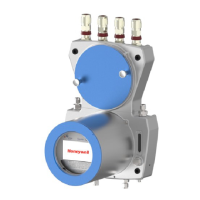
Gas connections (inlets / outlets and breathing elements)
The gas connections are pipe fittings and are equipped by the manufacturer.
The gas inlets are located at the bottom of the device. Left for process gas with integrated particle
filter. This inlet can also be used for test gas or verification gas. On the bottom right is the inlet for
the operational calibration gas. This inlet has no particle filter and is only suitable for connecting
particle-free gases.
The gas outlets are located on the upper side of the lower housing part, i.e. in the middle of the
device. On the right is the gas outlet for the vent gas from the measurement. On the left is the outlet
for gas that can flow through a bypass, e.g. if there are long supply lines and the reduction of the
reaction time is desired. The outflowing gas is discharged into separate vent lines for each outlet.
Two breathing points are used to enable atmospheric pressure equalisation between the inside of
the device and the environment. These breathing devices must not be closed or blocked. The main
breathing device is in the middle of the bottom, the auxiliary breathing devices are located on the
back of the device in the upper part of the housing.
Further information 5.3 Fluid installation of GasLab Q2
Electrical connections (cable inlet and connection circuit board)
Figure 3.2 shows an example of four cable glands for electrical inputs and outputs on the top of the
instrument. If required, the threaded holes of the housing can also be equipped with dummy plugs
or adapters.
The illustration shows, in the upper part of the instrument, also the connection box located below
the cable glands. It contains a circuit board with all electrical interfaces. These can be connected
with connection cables via plugs on the edge of the board. In the middle of the board is the
connection to the lower part of the housing. This connector is secured by barbs and must not be
removed.
The housing must be grounded or connected to the local potential equalization. For this purpose,
there is an earthing and equipotential bonding screw (GROUND) on the bottom next to the
calibration gas inlet. A further functional grounding point (FE) is in the connection box in the upper
recess of the board. See Figure 3.2.
Proper operation can only be guaranteed if all system components have the same ground potential.
Further information 5.4 Electrical installation
 Loading...