a. If both sides of the memory carrier contain the same capacity of memory, install the
next quad in side 0.
b. If side 0 contains more memory capacity than side 1, install the next quad in side
1.
c. If side 1 is full, install the remaining quads in side 0.
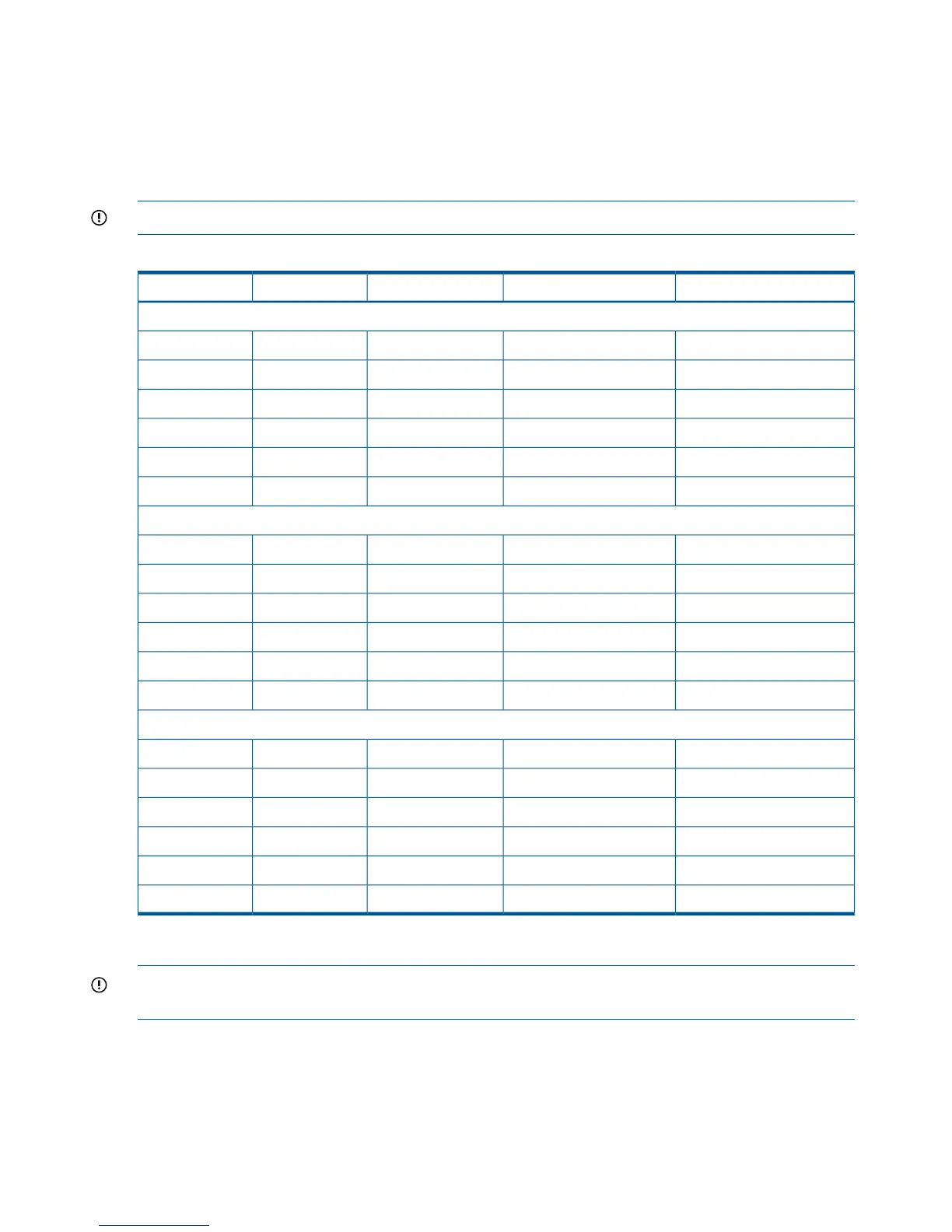
Table 74 shows several examples of proper memory carrier loading order.
IMPORTANT: The number in parenthesis indicates the order in which the quads are loaded.
Table 74 48-DIMM Memory Carrier Loading Examples
Memory Carrier Side 1Memory Carrier Side 0Quad Slot IDsQuad Number
Example 1
2 GB DIMMs (2)2 GB DIMMs (1)0A, 0B, 0C, 0D0
2 GB DIMMs (4)2 GB DIMMs (3)1A, 1B, 1C, 1D1
1 GB DIMMs (6)1 GB DIMMs (5)2A, 2B, 2C, 2D2
1 GB DIMMs (8)1 GB DIMMs (7)3A, 3B, 3C, 3D3
512 MB (10)512 MB (9)4A, 4B, 4C, 4D4
512 MB (12)512 MB (11)5A, 5B, 5C, 5D5
Example 2
1 GB DIMMs (2)2 GB DIMMs (1)0A, 0B, 0C, 0D0
1 GB DIMMs (3)1 GB DIMMs (4)1A, 1B, 1C, 1D1
512 MB (5)512 MB (7)2A, 2B, 2C, 2D2
512 MB (6)512 MB (9)3A, 3B, 3C, 3D3
512 MB (8)4A, 4B, 4C, 4D4
512 MB (10)5A, 5B, 5C, 5D5
Example 3
512 MB (2)2 GB DIMMs (1)0A, 0B, 0C, 0D0
512 MB (3)512 MB (6)1A, 1B, 1C, 1D1
512 MB (4)512 MB (8)2A, 2B, 2C, 2D2
512 MB (5)3A, 3B, 3C, 3D3
512 MB (7)4A, 4B, 4C, 4D4
512 MB (9)5A, 5B, 5C, 5D5
Installing Memory
IMPORTANT: You must pull the AC power plugs on the server every time you modify the DIMMs.
If you do not pull the AC power plugs, the system does not display the correct DIMM information.
To install memory, follow these steps:
1. Power off the server and disconnect the power cables. See “Powering Off the Server”
(page 90).
2. If rack installed, slide the server out from the rack until it stops. See “Extending the Server from
the Rack” (page 176).
210 Removing and Replacing Server Components