Table 62 PCI/PCI-X/PCIe Slot-Rope-ACPI Paths (continued)
Logical ACPI PathOLARD
Physical Rope
#Physical Slot #
Acpi(HWP0002,PNP0A03,100)/Pci(1|*)Yes19
Public, shared at 66 MHz.
Acpi(HWP0002,PNP0A03,100)/Pci(2|*)Yes110
Public, shared at 66 MHz
1
IMPORTANT: The new version of the PCI/PCI-X/PCIe backplane (version 1.1) shipped on July 1, 2008. For existing
servers, repair and replace should continue to be performed with the version 1 I/O backplane. For servers shipped as
of July 1, 2008, repair and replace should be performed with version 1.1 I/O backplane. The device paths for version
1.1 are as follows.
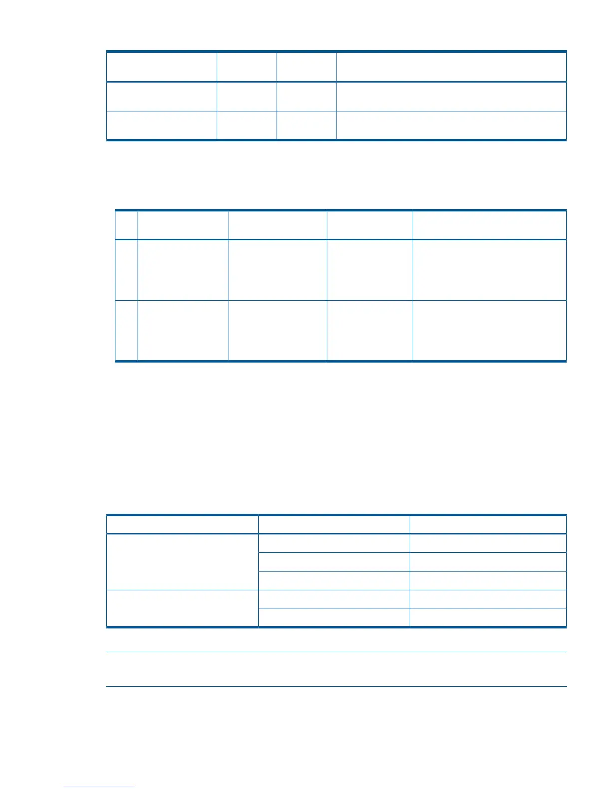
EFI Device PathHP-UX Device Path
Location as Viewed from
Rear of Chassis
Function Associated
with PathSlot
Acpi(HPQ0002,PNP0A08,600)/Pci(0|
0)/Pci(0|0)/Pci(1|0)/Pci(0|*)
0/6/0/0/0/0/1/0/03rd from leftI/O PCIe x8
(switched with slot 4)
Optional SAS core
I/O card
3
Acpi(HPQ0002,PNP0A08,600)/Pci(0|
0)/Pci(0|0)/Pci(0|0)/Pci(0|*)
0/6/0/0/0/0/0/0/04rd from leftI/O PCIe x8
(switched with slot 3)
Optional SAS core
I/O card
4
Management Subsystem (iLO 2 MP/BMC)
Manageability LAN LED on the Core I/O board CRU bulkhead
The manageability LAN uses two LEDs, viewable from the rear of the server. The manageability
LAN LED indicates link and activity status.
Only 10 Mb and 100 Mb speeds are currently supported on the manageability LAN.
Table 63
Table 63 Manageability LAN LED States and Speeds
LinkStatesLED
ActivityBlinking greenStatus
Link with no activitySolid green
No linkOff
100 MBSolid amberSpeed
10 MBOff
lists the manageability LAN LED statuses with their corresponding LED states.
NOTE: For information on the Core LAN LED, see “I/O Subsystem
(SAS/SATA/SCSI/DVD/HDD/Core I/O)” (page 168).
Manageability Reset Button on Core I/O Board FRU’s Bulkhead
The manageability Reset button, with pinhole access from the rear of the server, allows you to reset
the iLO 2 MP; it optionally also resets user-specified values to factory default values. A momentary
Management Subsystem (iLO 2 MP/BMC) 167