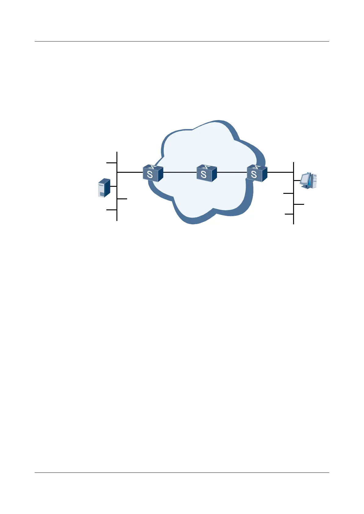
As shown in Figure 6-5, multicast services are deployed on the network. When SwitchC enabled
with the PIM GR function forwards multicast data to the receiver, the master MPU backs up the
PIM routes and Join/Prune messages to be sent to the upstream device to the slave MPU. When
the active/standby switchover occurs on SwitchC, the LPUs maintain the existing forwarding
entries to ensure uninterrupted forwarding of multicast data. The receiver can always receive
multicast data from the source during the active/standby switchover.
Figure 6-5 Networking diagram of PIM GR
Source
Ethernet
SwitchA
PIM-SM
SwitchB
Leaf networks
Ethernet
Receiver
HostA
SwitchC
GE2/0/0
GE2/0/0
GE1/0/0 GE1/0/0
GE1/0/0
GE2/0/0
Device Physical interface VLANIF interface IP address
SwitchA GE1/0/0 VLANIF 10 192.168.2.1/24
GE2/0/0 VLANIF 20 10.110.1.1/24
SwitchB GE1/0/0 VLANIF 30 192.168.2.2/24
GE2/0/0 VLANIF 40 192.168.4.1/24
SwitchC GE1/0/0 VLANIF 50 192.168.4.2/24
GE2/0/0 VLANIF 60 10.110.2.1/24
Configuration Roadmap
The configuration roadmap is as follows:
1. Configure the IP addresses and unicast routing protocols on the physical interfaces of the
switch matching the VLANIF interfaces.
2. Enable the unicast GR function on each switch and set the GR period.
3. Enable the multicast function, enable PIM-SM on the interface of the switch, and enable
IGMP on the interface connecting switch to the host.
4. Configure an RP. Configure same static RPs on the switches.
5. Enable the PIM GR function on SwitchC and set the GR period.
Data Preparation
To complete the configuration, you need the following data:
l Multicast source address 10.110.1.100
Quidway S7700 Smart Routing Switch
Configuration Guide - Multicast 6 PIM-SM (IPv4) Configuration
Issue 01 (2011-07-15) Huawei Proprietary and Confidential
Copyright © Huawei Technologies Co., Ltd.
215

 Loading...


