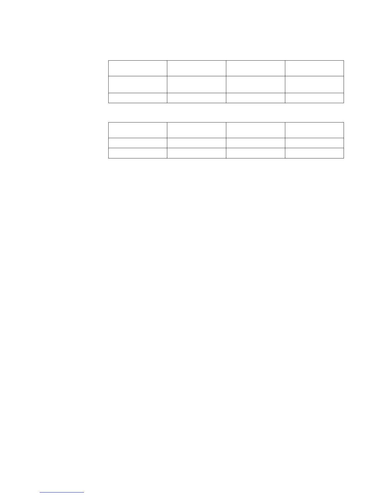
Table 23. Memory DIMM Type Numbers
Model Processor Feature
Code
Memory DIMM
Type
Location
830 All 3002, 3004, 3005,
3006, 3007
M02-s or M05-s
SB2 All 300F M02-s or M05-s
Table 24. Network Interface Controller (NIC) Card
Model Processor Feature
Code
HSL Controller Type Location
830, SB2 All 2732, 2754, 2758 M06
840, SB3 All 2737, 2755, 2759, 2770 M17
CDAWKLD
Too many communications lines are in use.
This ends the procedure.
CDTRAY
This symbolic FRU is not supported.
This ends the procedure.
CECPWR
The failing item is the power supply for the System Unit.
1. Is this system a Model 830 with SB2 System Unit and FC 9074 ?
Yes No
↓ Go to Step 3 of this procedure.
2. See “Locations — Models 830, SB2 System Unit with FC 9074 Base I/O Tower”
on page 709.
Replace the following FRUs in order one at a time until the problem is
resolved. See “Chapter 4. Removal and Installation Procedures” on page 617.
Note: Be sure to IPL in SLOW OVERRIDE mode after each replacement.
a. Processor regulator card in location M01 in the 830 System Unit.
b. Power supply in location PP1 in the 830 System Unit.
c. Power supply in location PP2 in the 830 System Unit.
3. This is a Model 840, SB3 System Unit and FC 9079 Base I/O Tower. See
“Locations — Models 840, SB3 System Unit with Processor Tower and FC 9079
Base I/O Tower” on page 719.
Replace the following FRUs in order one at a time until the problem is
resolved. See “Chapter 4. Removal and Installation Procedures” on page 617.
Note: Be sure to IPL in SLOW OVERRIDE mode after each replacement.
a. Processor regulator card in location M04 in the 840 System Unit.
b. Processor regulator card in location M07 in the 840 System Unit.
Symbolic FRUs
Chapter 3. Problem Isolation Procedures (PIPs), Failing Items, and Symbolic FRU Isolation 521